Building Description
Building Name
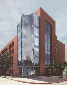
The Wilmer Eye Institute Outpatient Surgery and Lab Building
Delivery Method
Design-Bid-Build, GMP Contract with Whiting-Turner
Cost
$65M – Cost of Construction
$92M – Total Project Cost
Size & Occupancy
Total Building Floor Area...............................................................................202,350 GSF
Site Size........................................................................................1.6 acres = 69,700 SF
- Basement...........................................................................................31,100 GSF
Mechanical/electrical rooms, ahu’s, pumps
- First Floor..........................................................................................29,600 GSF
Outpatient surgical center with six operating rooms
Recovery/locker facilities, staff offices and atrium waiting room
- Second Floor......................................................................................28,950 GSF
Entrance lobby with security desk and elevator lobby
Atrium to roof with roof monitor
Open research laboratories and support spaces
Staff offices, toilets and break room
- Third & Fourth Floors..........................................................................27,850 GSF
Atrium to roof skylight
Open research laboratories and support spaces
Staff offices, toilets, break and conference rooms
- Fifth & Sixth Floors............................................................................27,850 GSF
Stairway and elevator access
- Roof Penthouse..................................................................................1,300 GSF
Stairway and elevator access
Location
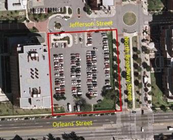
The building is located just west of N. Broadway between Orleans and Jefferson streets in downtown Baltimore, Maryland. It is the former site of an on-grade parking area.
To see the Johns Hopkins Medical Campus Map click here.
Start/Finish Dates
The planned timeframe for the construction of the Wilmer Eye Institute is from April 30, 2007 to October 30, 2009, which is 31 months with 657 working days.
Construction
General
The building will be built to the site property lines on three sides and due to other site constraints will require sheeting and shoring on all four sides. The base building design includes the construction of six levels above grade, a mechanical-room basement, and an underground tunnel connecting to an existing adjacent hospital facility.
As the construction site lies on the Johns Hopkins Medical Campus, all Johns Hopkins Hospital Rules and Regulations are to be adhered to at all times, including work hours (M-F 6:30 AM to 5:00 PM), noise limitations, cleanliness, safety requirements, outage requirements, traffic programs, access requirements, etc.) Any weekend work will require pre-approval by both the construction manager and the owner prior to work being planned or occurring.
Demolition
An existing paved parking lot, as well as several spread footings from a prior structure will need to be removed before construction begins. It is also anticipated that parts of Orleans and Broadway streets will need to be reconstructed due to the proximity of the site to the existing roadways. An existing curb cut and driveway on Orleans Street will be removed and replaced with a sidewalk and grass strip to match the existing conditions of the north side of Orleans Street. The west curb, sidewalk and landscaping along N. Broadway will also be replaced if necessary.
MTA Metro Tunnel
There is an existing MTA Baltimore Metro tunnel running underneath North Broadway Street. It runs parallel to the east side of the site and begins to curve to the west as it passes south of Orleans Street. The outer limits of the westernmost track clip the northwest corner of the Broadway and Orleans right-of-way. The top of track elevation here is approximately 30 feet and the top of the tunnel lining is at approximately 47 feet. Investigation of the tunnel’s as-built drawings will be required to confirm the location of the tunnel and plan for underpinning and soil modification methods.
Material Staging
Due to limited staging area, all material shall be delivered to the project in such quantities and at such times as required for its timely installation. Extra care must be taken to minimize trucks/vehicles “standing” on the roadways while waiting to make deliveries or pick-ups. It is imperative that emergency vehicles (ambulances, fire engines, etc.) have full, unimpeded access to all JHH Facilities at all times.
Site Access
Access to the jobsite will primarily be from Orleans Street. Access to site prior to 6:30 AM daily will be prohibited due to noise limitations. Upon completion of the underground tunnel, construction traffic will enter the site from Orleans Street and exit through another gate onto Jefferson Street.
Construction Conveying
Material conveying will be accomplished with a tower crane built by the concrete contractor during the construction of the spread footings. It will be removed after the completion of the superstructure, at which time a man and material lift will be installed on the building’s west elevation.
Adjacent Facilities
The project site is in close proximity to the existing JHH Cancer Research Building 1. This building is fully occupied and access to the entrance of this building must be maintained at all times. The contractor is responsible for ensuring minimum interference with roads, walkways, and other adjacent or used facilities.
Building Enclosure/Interior Work
An effort will be made to enclose the building as soon as possible, making it reasonably weather-tight so that interior rough-in and fit-up work can commence as early as achievable. Work will proceed concentrating on the lab areas first, followed by the offices. Rough-in work must proceed on each level as soon as the concrete contractor’s re-shores are removed from that floor. Work on successive floors is intended to keep pace with the concrete work.
Temporary Lighting/Power
There will be no temporary electrical power or lighting in place until installed by the electrical contractor by December 1, 2007. Until then all trade contractors must provide their own power/lighting. Temporary electrical service will be 1200 ampere, 480 volt, 3-phase, 4 wire, and will be extended and properly distributed into the building as soon as possible.
MBE/DBE/WBE Participation and 1st Source Hiring Program
This project is aimed to support minority, disadvantaged and women’s business enterprises. The MBE/DBE/WBE participation goal for this project is 18%. The First Source Hiring Program was established to provide employment opportunities to residents of the local area. The construction manager is required to have an individual assigned to be the MBE/DBE/WBE First Source Hiring procurement officer on the project.
Architecture
Several unique architectural features of the new facility stand out among the rest. The first is the reflective glass curtain wall over the entrance on the northeast corner of the building. The large glass wall will reflect the image of the former Wilmer’s “mini” dome as you enter, symbolically and visually bridging the 83-year-old Institute’s old and new presence on Hopkins’ East Baltimore campus.
The other main feature of the building is the presence of a central atrium in the lobby/entrance area. The space stretches from the first floor to roof of the building overtop of the lobby and the main hallway.
The building has a primarily brick façade aside from the glass curtain wall. There will be two building entrances, each one story apart, adhering to the natural slope of the site. An 8’x10’ service tunnel between Wilmer and the basement corridor of Cancer Research Building 1 will connect to a loading dock/receiving facility being constructed to the west of Cancer Research Building 1. There will be on-grade parking for 24 cars adjacent to the building and will be accessed from an existing curb cut on Orleans Street.
Building Envelope
Exterior Walls
The primary exterior wall system will be modular extruded type FBX brick in cavity wall construction with CMU back-up. Each of the window openings on the south and east walls use jack-arches and brick returns to create an 18-inch deep frame. Window sills will be cast stone. 7-ounce copper laminated type through-wall flashing will be installed in conjunctions with plastic tube type weeps spaced 24”O.C. horizontally. Anchors will be two-piece stainless steel type, spaced 16” O.C. vertically and 24” O.C. horizontally.
The exterior soffits will be aluminum panels finished with a factory applied 3-coat fluoropolymer in custom color. Cavity wall insulation will be extruded-polystyrene board insulation. Foil faced batt insulation combining mineral fibers with thermosetting resins will comply with ASTM C 665, Type III, Class B. Foil faced slag-wool-fiber board safing insulation will also be in place.
Exterior Windows
Typical glazing will consist of 1-inch insulating spectrally selective glass with SHGC (shading heat gain coefficient) exceeding the requirements of ASHREA 90.1. Typical glazed curtain wall windows will be thermally broken, finished in a 3-coat fluoropolymer finish and will be performance tested to the owner’s specific criteria. The curtain wall at the north and south ends of the atrium will contain 60 motorized windows as a smoke control system.
Skylight/Glass Canopy
The skylight will be thermally broken aluminum framed and single-sloped finished in a 3-coat fluoropolymer finish of custom color, factory applied. Skylight glazing consists of a laminated safety glass assembly meeting the above mentioned typical criteria for glazing.
The exterior canopy will have a tube steel frame with ornamental metal supports back to the building façade. The canopy will be field painted, contain overhead laminated safety glass, and will be equipped with a dry sprinkler system.
Exterior Doors
Thermally broken stile and rail aluminum doors in aluminum framing will have a 3-coat fluoropolymer finish and will match storefront entrance. Bi-parting automatic sliding doors will have fixed sidelights and will also match storefront entrance.
Exterior utility doors utilize hollow metal frames with mitered or coped and continuously welded corners, fabricated from 0.0635-inch (1.6 mm) thick galvanized steel sheets, factory primed and field painted. 1-3/4-inch (44 mm) thick steel doors are Level 3 and physical Level A (Extra Heavy Duty).
Roofing
Single ply roofing shall be Sarnafil System 1000 IRMA (insulated roof membrane assembly), loosely laid over sloping concrete deck consisting of a leveling layer, thermoplastic polyolefin sheet roofing membrane, protection layer, drainage panel, extruded polystyrene insulation, filter fabric and pavers. Sheet metal flashing and trim will be stainless steel, type 302/304, 28 gage. The building will be provided with roof anchors to facilitate window cleaning and general building maintenance from suspended equipment.
Engineered Systems
Structural
The building has an overall rectangular shape, with the longer side running along North Broadway. Column bays are typically 32’-0” by 21’-0” to accommodate the proposed laboratory modules. Column spacing is reduced to 10’-6” on the north side of the building to allow for the use of lateral frames. The basic footprint of the building consists of eleven 21’ spans and four 31’-6” spans to make up approximately 29,000 square feet.
The building’s primary structural system utilizes a mildly reinforced two-way concrete plate system. This basically consists of flat floor plates with additional depth in the form of drop panels near the columns. The typical rectangular shape of the bays works fairly well with this system.
Lateral load resistance will require the use of several shear walls. They will be 12” thick and will run from the foundation up to the roof. There will be approximately 70 linear feet of shear wall per floor.
Typical slab depth is 9½” with 5½” drop panels at the interior columns and 7½“ drop panels at the exterior columns. Typical column size is 21”x 21” from the third floor up, and 24”x 24” in the basement and first floor.
Beams, columns, and spread footings will all be reinforced concrete. Perimeter walls will be modular brick façade with CMU backup. Floor to floor distance is 15’-4” on the first floor, 25’ in basement, and 14’-8” on the remaining levels.
It should also be noted that the building has been structurally designed to be able to support a three future expansion without major reconstruction.
Approximate Reinforcement Quantities:
- Slabs
- 5.10 psf typical
- 6.00 psf Roof level (future 7th floor)
- Beams
- 20 plf, approx. 300 linear feet per floor
- Columns
- Shear Walls
- 5.0 psf (per shear wall area, typical)
- Basement Walls
- 9.5 psf (all basement perimeter walls)
- Tunnel
- 12” thick walls with 170 plf of reinforcing
- Concrete Strength
- 4,000 psi typical
- 5,600 psi for interior and basement columns)
- Reinforcing Steel
Mechanical
System Overview
The mechanical system has been designed to serve laboratory, clinical and office spaces. All central utilities including chilled water, steam, domestic water, natural gas, oxygen and both normal and emergency power will be branched off campus central utilities. There will be separate air-handling systems serving the laboratory, clinical and office areas, and all will be variable air volume (VAV). Services such as water, vacuum and air will be separated for the laboratory and clinical areas through cross contamination devices or dedicated equipment. A common redundant AHU will back-up the clinical and laboratory spaces. The exhaust fan system for the laboratories will be designed with a redundant exhaust fan, and the chilled and heated water systems will be designed to support energy recovery wheels.
All air distribution systems have been designed to allow flexibility for future redesign, primarily through accessibility to the duct systems throughout the air distribution system and by providing symmetry and uniformity in the branch duct layout.
All HVAC equipment with the exception of the central laboratory exhaust fans will be located at the basement level. The exhaust fans will be located on the roof within a screened enclosure. Outside air for the AHU’s in the basement will be ducted from the second floor of the building.
Distribution
Central shafts at either side of the building will convey ductwork and service piping to all of the floors. Terminal units will be located over the areas they serve both in the clinical and laboratory areas. Piped services will be further distributed through the ceiling spaces for distribution within the laboratories via a horizontal service chase within the laboratory benches.
Air Handling
Four 44,000 CFM 100% outdoor air industrial grade air handling units with a 40” diameter DWDI fan sized for 10” static pressure will serve the lab areas (8” static pressure for the clinical floor, and 6” static pressure for the atrium/office area). Four 66” diameter SWSI laboratory exhaust fans sized for 70,000 CFM each will be located on the roof, discharging at 10’ above the main roof line.
Steam Service
The maximum steam load, including process loads, is estimated at 42,000 lb/hr with the incorporation of energy recovery wheels on the laboratory AHU’s. A parallel steam reduction station will be used to reduce the incoming steam pressure from 120 PSIG down to 65 PSIG for domestic and industrial steam-to-hot-water converters, as well as down to 15 PSIG for HVAC steam-to-hot-water converters. System HVAC heating will provided by four steam-to-hot-water converters, two pre-heat exchangers and two re-heat exchangers, each sized for 66% of their respective total loads. The pre-heat exchangers have been sized for 2905 MBH and the re-heat exchangers will be sized for 6085 MBH. Redundant pre-heat pumps will be end suction type sized for 195 GPM at 80 feet of total dynamic head, and the re-heat pumps will also be end suction type sized for 405 GPM at 80 feet total dynamic head. The pump system will have variable frequency drives. There will be two stainless steel steam-to-steam generators for clinical use. The distribution piping to the sterilizers and humidifiers will also be stainless steel. Condensate from the incoming steam and building usage will return to the central plant. Heating water will be distributed to terminal heating equipment and central air handling equipment that uses 100% outdoor air. Humidification will come to the central air handling system for both the laboratory and clinical AHU’s. Steam filters rated for 3 micron particle removal will be used in all critical equipment.
Cooling
The preliminary total cooling load has been estimated to be 1,612 tons after the incorporation of energy recovery wheels. Chilled water to satisfy this load will be routed from the campus utilities through decoupled tertiary pumps. It will distributed throughout the building by three tertiary pumps sized 1075 GPM at 80 feet of total dynamic head, each with variable frequency drives sized for 50% of design load. A system pump bypass will be in place for emergency use. All chilled water piping and pumps will be designed to optimize the efficiency of the energy recovery wheels.
Laboratory Equipment
One supply and exhaust terminal unit has been provided for each two lab modules and has been sized to accommodate a 6 foot chemical fume hood. Support spaces will house supply and exhaust terminal units where pressurization control is required in both the clinical and laboratory areas. Areas with high internal equipment gains exceeding 30 W/sf have been provided with supplemental cooling only fan coil units where appropriate. The fume hood and bio-safety cabinet designs are constant volume. The bio-safety cabinets will also utilize thimble connections designed for 120% of the cabinet’s rated flow.
Environmental Controls
The facility will be environmentally controlled by a pneumatic-electric, direct digital control (DDC) system by Andover. Central systems will employ a direct digital control system with pneumatic driven terminal devices. The DDC system will have a fiber optic connection to the Woods Basic Science Building, a facility which serves as the control hub for the entire medical campus.
Electrical
Overview
Electrical lines will be distributed throughout the building via conduit and wire systems. Feeders and branch circuit wiring will be encased in electrical metallic tubing (EMT) except in outdoor/hazardous locations which will use rigid steel conduit or Intermediate Metallic Tubing (IMT). Raceways encased in concrete will be Schedule 40 PVC.
It should be noted that all transformers, ductbanks and feeders have been sized to accommodate a future three-floor expansion.
Normal Power
Two redundant 13.2 KV feeders from the hospital’s distribution network will supply normal operational power. The feeders will be run to the building via rigid steel conduits and underground concrete encased 4” PVC ductbanks. They shall be 15KV shielded size #4/0 with a 600 volt insulated ground conductor. The new ductbank will tie in with an existing system under Jefferson Street and will be approximately 300 feet in length.
A double-ended substation will transform the feeder service to 480/277 volt, 3 phase, 4 wire for distribution throughout the building. It will include 15 KV fused primary switchgear, 2,500 DVA silicon filled transformers as well as secondary distribution switchgear.
One 300 KVA dry type, shielded isolation transformer with K13 rating will be provided on each floor. Distribution panel boards rated at 600 amperes will be provided for supply to the branch circuit panel boards located in the laboratories and offices. Operating rooms will have two 2.75 or 5 KV 277/120 volt isolated power panels per room and sized to support the equipment loads. Switchboards and variable-frequency drives (VFD’s) will be in place for the basement mechanical equipment as necessary.
Emergency Power
A 13.2 KV underground emergency feeder will be run in from the hospital’s South Generator Plant. The feeder will be three single conductor #4/0 15KV shielded cables and one #4/0 600 volt insulated ground conductor in an underground PVC encasement. The length of this feeder/ductbank is approximately 700 feet. It will feed into a single-ended substation in the basement that contains a 1000 KVA transformer with a secondary 480/277 volt, 3 phase, 4 wire system for distribution to the emergency switchboard.
In the event of a power outage, automatic transfer switches will reroute the electrical load from normal to emergency source. The switches will be isolation bypass type to allow for routine maintenance, and each will have Square D power meters installed.
Emergency power will be distributed throughout the building by a system of panel boards and feeders. Power will divert to life safety branch loads, critical loads on the Surgery Level and equipment branch loads as needed.
Isolated Ground
An isolated ground system will be provided for the protection of sensitive electronic equipment. A ground cable riser originating at the building main ground field will route upward through the building. A ground cabinet will be placed on each floor with a copper ground bar pre-drilled for the connection of ground cables from lab/computer equipment.
Transient Voltage Surge Suppression
Transient Voltage Surge Suppression (TVSS) measures will be in place to protect the building’s electrical systems from external power surges and lightning strikes. 208/120 volt distribution panel boards will be protected from internal transients by TVSS equipment rated for category B3 environments in accordance with IEEE C62.41. Service entrance equipment will have a one-time surge current rating of 120,000 amperes, and branch channel equipment will have a rating of 80,000 amperes.
Lightning Protection
The building will have lightning rods mounted along the top perimeter of the building on the parapet walls. The rods will have dedicated ground conductors routed down the building to copper ground rods in the earth.
Telecommunications
Telecommunications system design will be up to par with Johns Hopkins’ standards. Raceways for communication systems wiring will be provided throughout the building, as well as a communications closet on each floor in a stacked pattern to allow for vertical distribution. A minimum of four 4-inch conduits will be run through the floor at each level. Cable trays will be aluminum ladder style and will be provided in corridor spaces. The main distribution frame room will located in the basement.
Security
The building will be equipped with security equipment supplied by Hopkins, including security doors and a closed-circuit television (CCTV) system with four outdoor perimeter cameras. Cameras will have full pan, tilt and zoom capabilities and their monitors will be located at the security desk in the main lobby/entrance area.
Lighting
Fluorescent lighting fixtures will be found throughout most of the project to provide energy efficiency and easy maintenance. Incandescent and tungsten-based lighting will be used in areas that require special appearance and dimming capabilities. High-ceiling areas, mechanical spaces and exterior applications will utilize high-intensity discharge (HID) metal halide lamps.
Fluorescent fixtures will use T8 lamps and solid-state electronic ballasts with a total harmonic distortion limit of 10 percent. Furthermore, fluorescents will have a minimum color-rendering index (CRI) of 80 and a color temperature of 3,500 Kelvin. Metal halide fixtures will use coated lamps, and parabolic louvers shall be of low iridescent type.
Exterior lighting must provide adequate security and building access. Walkway and plaza lighting will be decorative, pole mounted HID fixtures in accordance with Johns Hopkins Hospital’s guidelines. The building façade will be lit with a combination of HID floodlights and wall mounted decorative sconces.
Interior office and laboratory space light fixtures will generally be controlled by wall-mounted occupancy sensor switches. General circulation and exterior lighting fixtures will be controlled by the building’s energy management system. Restroom lighting will be controlled via ceiling mounted occupancy sensors.
Fluorescent lighting with dimming capabilities will use dimming ballasts and controls. They will have 1 to 100 percent dimming range, UL listing, Class P thermal rating and Class A sound rating.
Emergency lighting will run off the building’s emergency power system. In the event of an outage, dedicated fixtures will light the corridors, lobbies, toilet rooms, stairs, etc. Exit signs will be lit by highly energy efficient light emitting diodes (LED’s).
Plumbing
Site Utilities
Utility piping, structures and installation shall be in accordance with the City of Baltimore Department of Public Works Specifications, dated, 2006, and Book of Standards.
An 8” water service and meter from Broadway Street will be installed to provide domestic water and fire protection. In accordance with city standards, the piping will be class 54 ductile iron pipe with harnessed joints.
A proposed 12” RCP private storm drainage connection to transmit roof drainage will extend from an existing inlet in Jefferson Street to the north wall of the new building. The parking area will drain into a concrete sandfilter water quality structure at the south end of the parking lot. The sandfilter will then connect to the existing storm drain manhole constructed during the CRB I project at the southwest corner of the site.
8” DIP Class 52 sanitary services will extend from an existing manholes (also constructed during the CRB I project) and enter at the southwest corner and the north wall of the new building.
According to geotechnical study, the groundwater elevation is anticipated to be at elevation 35-ft. The current lowest floor elevation is at elevation 50-ft, approximately 15-ft above the groundwater elevation. Therefore, a special below-slab subdrainage system will not be needed. However, a perimeter foundation drainage system around all below grade walls will be required.
Roof Drains
Roof drains will empty into rain leaders that run vertically through the building and dump into the storm sewer. Where possible, condensate from air handling units will tie into the storm system as well. Storm water that finds its way to the sub-basement will be pumped to a gravity storm main that is located outside the building. Foundation drain tile will also be pumped by a pump station on the building’s exterior.
Domestic Water Supply
Domestic cold water will be provided through a 10-inch combined domestic and fire protection feed service that is separated with a backflow preventer. It will be moved by a 200 GPM triplex domestic water booster pump with a 65 PSIG boost. Domestic hot water and laboratory hot water will be provided by two 25 GPM steam hot water heaters and two 50 GPM steam hot water heaters, respectively. Mixing valves will be provided for each system, as well as the use of independent backflow preventers to separate domestic, laboratory and mechanical make-up water systems. Piping for both systems will be seamless copper water tube, ASTM B 88, Type L, Hard. Fittings will be copper solder joint fittings, 150 lb, ANSI B 16.22-73. Joint solder shall be ASTM B32-78 tin-antimony 95-5.
Drain Waste Vent
Laboratory waste will be directly connected into the sanitary sewer line at the base of the vertical lab stacks. Any toxic, radioactive or high concentration wastes will be disposed of through local “in-lab” safety containers, without the use of piped systems. Vertical toilet stacks will be cast iron no hub type with sanitary risers as needed. Sanitary piping from the labs to the base of the vertical stack will be an Enfield polypropylene mechanical joint piping system. The basement and clinical floors sanitary will need to be pumped to an exterior gravity sanitary drain system.
Sanitary/Sump Pumps
Duplex 20 GPM storm water sump pumps and sanitary sewage ejector pumps will be provided for storm water or sanitary flows that cannot be drained by gravity. All elevators will be equipped with a simplex 10 GPM oil miser sump pump. All pumps will have NEMA 1 standard controls.
Gas Systems
Natural gas service feeds will be run through the mechanical shafts and terminated via valve and cap. Service will later be extended to the labs as required. Specialty laboratory gases, such as N2, will be delivered, handled and distributed from cylinders located just outside the building. The anticipated system will consist of 2-5 cylinders with back-up manifold assemblies. Oxygen and nitrous oxide will be provided through one-inch service piping extended from the Outpatient building across Jefferson Street by a buried schedule 40 PVC conduit system approximately 200 feet in length. Natural gas piping will be black steel pipe, ASTM A 120-78, ANSI Schedule 40, with joints according to the American Standard for piping threads ANSI B2.1-68. Specialty gas piping will be the same as the vacuum system.
Central Compressed Air
Both the laboratory and clinical areas require a supply of dry, oil-free compressed air capable of providing 100 PSIG. The lab system is anticipated to be a duplex 36 SCFM system, while the medical air system is estimated to be a duplex 25 SCFM. Piping will be the same as the domestic water supply, with the exception that the piping is labeled for oxygen service and sealed when delivered to site, and that the joints shall be brazed silver alloy brazing.
Vacuum System
Similar to the compressed air system, both the laboratory and the clinical areas will require separate water ring vacuum systems capable of providing 20 inches of vacuum pressure. The lab system is estimated to be a triplex 172 SCFM system, and the clinical to be a triplex 70 SCFM. Piping, fittings and joints shall be the same as the central compressed air system.
Reverse Osmosis (RO) Systems
A centralized reverse osmosis (decontaminated drinking) water system with a continuous loop design capable of providing one mega-ohm resistivity has been recommended for the facility. The piping system for this water will be a socket or butt fused pigmented polypropylene plastic piping system with true union diaphragm valves at the points of use.
Fire Protection
The building will have complete sprinkler coverage by a combination wet sprinkler-standpipe system. A 1250 GPM electric fire pump will be required to maintain 100 PSI at the top of the standpipe systems, which will be located at the stairwells with floor control valves extending from one stairwell only.
A complete fire detection and alarm system will be in place as well. The system will include a Fire Command System with voice communications and AHU control capabilities, smoke detectors, heat detectors, audio-visual devices and other associated measures throughout the entire building. The main entrance will be equipped with a central graphic annunciator panel to be monitored by Johns Hopkins Hospital’s Facilities Department. All wiring for the system will be installed in a dedicated conduit system.
Fire safety considerations have also been accounted for in the design of the building’s central atrium. The curtain wall at the north and south ends of the atrium will contain 60 motorized windows, and two 80,000 CFM exhaust fans will be a dedicated smoke control measure. The motorized windows will be connected to the emergency power and fire alarm systems so as to be interfaced with the smoke evacuation system. The atrium will also be equipped with a deluge system that covers both sides of the structural separation glass between the laboratory and atrium spaces.
Zoning & Codes
There exists a PUD (Planned Unit Development) zoning requirement in the area that limits the height of the building to 80’ (as measured from grade at the intersection of Broadway and Orleans). Johns Hopkins Hospital is pursuing an amendment to the PUD to increase this height limitation, possibly allowing the addition of three extra floors at a later date.
Applicable Building Codes
Building, Fire, and Related Codes of Baltimore City (July 31, 2006)
International Building Code (IBC), 2000 Edition
Americans with Disabilities Act Accessibility Guidelines (ADAAG)
Published July 23, 2004
Building Code Requirements for Structural Concrete, ACI 3-18
National Fire Protection Association (NFPA) National Fire Codes (NFC)
- NFPA 101, Life Safety Code (LSC), 2003 Edition
- NFPA 45, Standard on Fire Protection for Laboratories Using Chemicals, 2000 Edition
- NFPA 13, Installation of Sprinkler Systems, 2002 Edition
- NFPA 14, Standard for the Installation of Standpipe and Hose Systems
- NFPA 72, National Fire Alarm Code, 2002 Edition
- NFPA 30, Flammable and Combustible Liquids Code, 2002 Edition as referenced by NFPA 45
Should a conflict between the IBC and NFPA codes occur, the architect has proposed that the more restrictive of the two requirements will be applied.
Electrical Codes and Standards:
- National Electric Code 1999
- ANSI/ASME A17.1, Safety Code for Elevators and Escalators
- ASHRAE/IESNA 90.1 – 1999, Lighting Requirements
- ANSI C-2, ANSI C-37, National Electric Safety Code
- IEEE, Institute of Electrical and Electronics Engineers
Mechanical Codes and Standards:
- 2000 International Building Code with 2003 Baltimore City Supplements
- 2000 International Mechanical Code
- 2001 National Standard Plumbing Code
- 2000 International Fire Code
- 2000 International Energy Code
- ASHRAE Handbooks
- ANSI/AIHA Z9.5-1992 American National Standard for Laboratory Ventilation
- AIA Hospital Guildelines
|