Redland Technology Center
Rockville, MD
| |
| Home |
| Student Bio/Resume |
| Building Statistics |
| Thesis Abstract |
| Technical Assignments |
| Thesis Research |
| Thesis Proposal |
| Presentation |
| Final Report |
| Reflection |
| Senior Thesis e-Studio |
Note: While great efforts have been taken to provide accurate and complete information on the pages of CPEP, please be aware that the information contained herewith is considered a work‐in‐progress for this thesis project. Modifications and changes related to the original building designs and construction methodologies for this senior thesis project are solely the interpretation of Shawn Pepple. Changes and discrepancies in no way imply that the original design contained errors or was flawed. Differing assumptions, code references, requirements, and methodologies have been incorporated into this thesis project; therefore, investigation results may vary from the original design.
Building Name: Redland Technology Center
Building Location: 540 Gaither Road, Rockville, MD 20850
Building Occupant: Not currently leased, under construction
Type of Building: Two office buildings with stand-alone parking garage
Total Square Footage:
Building 2: 210,240 SF
Building 3: 136,430 SF
Parking Garage: 314,600 SF
Number of Stories:
Building 2: 9 levels
Building 3: 6 levels
Parking Garage: 6 levels
Primary Project Team:
Owner: |
Perseus Realty, LLC |
Construction Manager: |
Clark Construction Group, LLC |
Architect: |
DNC Architects, Inc. |
MEP Engineer: |
Meta Engineers, P.C. |
Structural Engineer: |
Smislova, Kehnemui & Associates, P.A. |
Civil Engineer: |
The RBA Group |
Construction Period: January 2008 – June 2009
Project Cost: $52,800,000 Negotiated GMP
Project Delivery Method: Design-Bid-Build
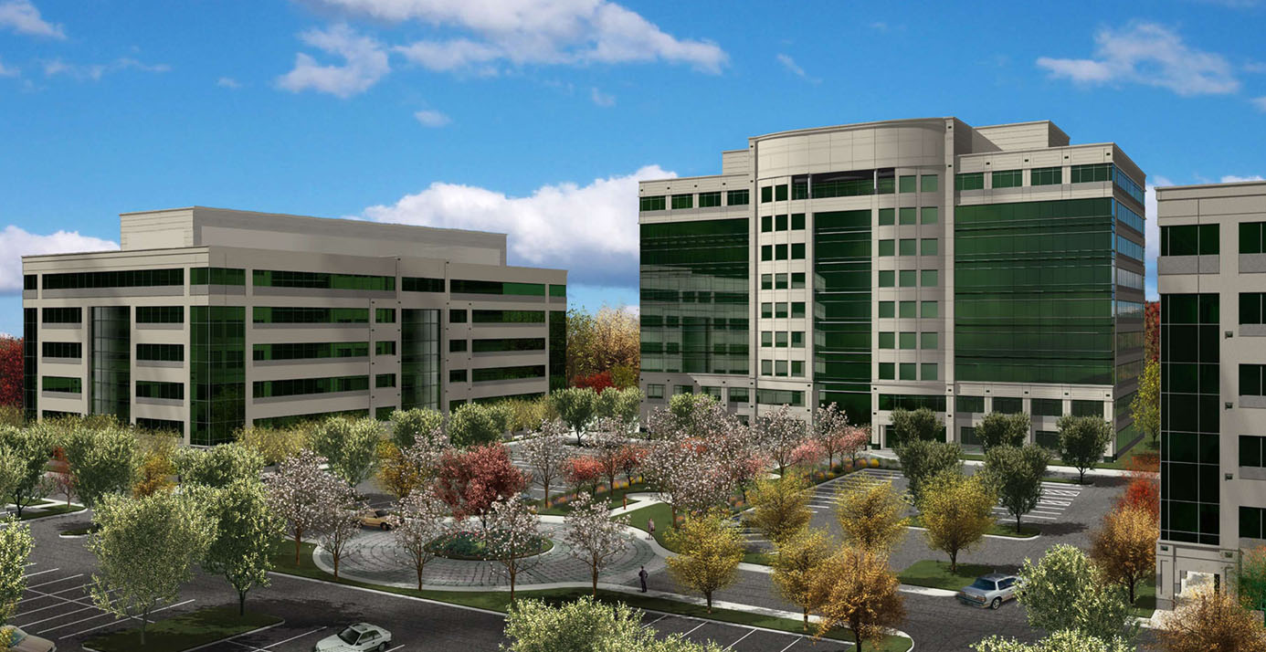
Architectural Description:
The Redland Corporate Center consists of three office buildings and a 1,115 space parking garage situated on a 24.5 acre in northern Rockville, MD. The site is conveniently located along the I-270 corridor and near Shady Grove Metro station of the Washington D.C. metro system. The James G. Davis Construction Corporation built the first office building, phase 1, in 2004. Building 2 and 3 and the parking garage are currently being constructed.
The three office buildings consist of an architectural precast concrete panel façade with glass curtain wall ribbon windows. Building 2 has 9 floors of office space with 5 elevators, including 1 service elevator. Building 3 has 6 floors of office space with 3 elevators, including 1 service elevator. Both buildings feature efficient floor plans with large column free office areas. The corners of each building are built with cantilevered structural steel and concrete decks to provide column free corners. There is an outdoor balcony in Building 2 on the 9th floor that gives great views of the complex and the nearby neighborhoods. Building 2 has a state-of-the-art fitness center with fully equipped locker rooms and a café for the tenants’ convenience.
Mindy Weisel, a Washington D.C. area glass sculptor, has been commissioned to create glass sculptures for the project. These glass sculptures will mainly be displayed outside in the patio area between Building 2 and 3 and also in the lobby of Building 2.
Codes: 2003 International Building Code
2003 NFPA 101 Life Safety Code
1996 International Mechanical Code
1996 NEC National Electirc Code
1997 International Plumbing Code
1986 ANSI A-117.1 Handicapped Code
City of Rockville Zoning Ordinance
ADA Architectural Barrier Removal & Compliance Manual Based on Maryland Accessibility Code
Zoning: Mixed Use Employment (MXE)
Historial Requirements: N/A
Building Envelope Description:
The façade consists of 5½” thick precast concrete panels with glass curtain wall ribbon windows. The roofing system consists of a full adhered EPDM rubber (ethylene propylene diene M-class rubber) sheet roofing membrane roofing system over multiple layers of rigid insulation boards secured to low sloped metal roof decking.
Construction:
The Redland Tech Center project site is located in the middle of a residential neighborhood and beside the occupied Building 1 office building. During construction, Clark needs to be sensitive to the community environment around it. There are noise ordinances in effect between 7 pm and 7 am through the weekdays and between 5 pm and 10 am on the weekend. There are many construction material deliveries to the site and Clark needs to ensure that they do not block the flow of traffic through the community and especially through the parking lot shared with Building 1.
Construction at the Redland Tech Center project is a fast paced 18 month schedule. During this construction period, all three buildings are being constructed concurrently. The site has limited lay down area for staging of materials and space between buildings is limited, only 30’. This leads to many coordination problems between the construction activities of each building. For example, the foundation walls of the parking garage had to be braced so a mobile truck crane could pass between the two buildings and erect the precast façade for Building 2.
Most of the utilities for the expansion of the Redland Tech Center already exist. These utilities were installed during the construction of Building 1 by Davis Construction. Clark Construction had to relocate one existing storm water line and tie the existing utilities into the new buildings.
Structural Steel:
Redland Tech Center Building 2 is a 9 story structural steel office building with a braced frame to resist lateral loads. The steel fabricator and erector, Strait Steel, Inc. of Greencastle, PA, erected the 1,300 tons of steel in Building 2 in 3 months by a 150-ton crawler crane. Due to the size of crane used and sequencing method, Strait was able to use one pick location and lay down area during the erection of Building 2. The typical column size of the structure ranges from a W14x311 section at the first floor to a W14x43 section at the penthouse level. The typical beam size is a W21x44. Typical bay size is 30’ x 30’. Building 2 uses a 3” composite metal deck system for the elevated floor slabs. Building 2 has 3 braced frames in the West-East direction and 2 braced frames in the North-South direction. Each braced frame uses 12” pipe in conjunction with the beams and columns to complete the lateral resisting system.
Cast-in-Place Concrete:
The extent of cast-in-place (CIP) concrete work for Building 2 is limited to the caissons, grade beams, slab-on-grade (SOG), and elevated slabs. There are 46 caissons in Building 2 with a diameter ranging from 30” to 78”. The caissons used 3,500 psi concrete. Typical caisson depth is approximately 30’. The grade beams also used 3,500 psi concrete and ran only between the outer perimeter of columns. The SOG is a 5” thick normal weight concrete slab. The elevated slabs are a composite metal deck system with 3” thick deck and 3” thick light weight concrete. A pump truck was used to place all concrete.
Precast Concrete:
Arban and Carosi, Inc. supplied the architectural precast façade panels for Building 2. There were 292 panels needed to cover the exterior of the building. All the panels were cast in Arban’s yard in Woodbridge, VA. The panels were erected by a 50-ton truck crane with a 150’ boom and a 50’ jib. Arban worked in a clockwise manner around the building and positioned the crane as needed to best erect the panels. The panels use bolted connections to connect to the clips welded to the steel structure.
Mechanical System:
Each floor of the building has its own mechanical room with a self-contained air conditioning unit (SCU) to control the environment in the tenant and common spaces. Each SCU flows on average 24,750 CFM. There are 3 water cooling towers on the roof. This system uses forced air through medium pressure ductwork to supply conditioned air to the building. Variable air volume (VAV) units are used throughout each floor to meet the tenant’s needs more efficiently. There are separate heat pump systems for the café, fitness center, and elevator machine room.
Electrical System:
Two 2,500 amp, 460Y/265V service feeders provide electricity to the building. Each service runs into a common electrical room on the first floor where the power is distributed throughout the building. Two 2,000 amp, 460Y/265V copper bus ducts supply power to the upper floors. There are three transformers to step power down to 208Y/120 for tenant use. A 600KW, 480Y/277 diesel generator is located in a separate structure behind the building and will provide emergency power should the power grid fail. Lighting fixtures are mostly 277V fixtures manufactured by Lithonia.
Curtain Wall:
Building 2, unlike Building 1 and 3, has extensive curtain wall on its front façade, along with ribbon windows on the other three faces of the building. Only Building 2 has the curtain wall because it is the feature building of the complex and is meant to stand out from the other two buildings. The system includes prefinished aluminum frames with green tinted glazing. Depending on the location of each piece of glazing, the transparency of the glazing varies. The glazing is less transparent at floor level to block the view of the concrete slabs from the outside of the building. The curtain wall and ribbon windows were installed from the exterior of the building with workers working from swing stages. Due to the simplicity of the curtain wall for this project, the architect was able to design the system without needing a design-build contractor like some other complex projects would need.
Fire Protection:
Building 2 and 3 have automatic wet pipe sprinkler systems throughout the entire building. Each floor is to have a separate zone for each floor. Two standpipes provide water to the upper floors. Spray-applied fireproofing is used to protect the structural steel framing system. The fireproofing is of the mineral fiber type.