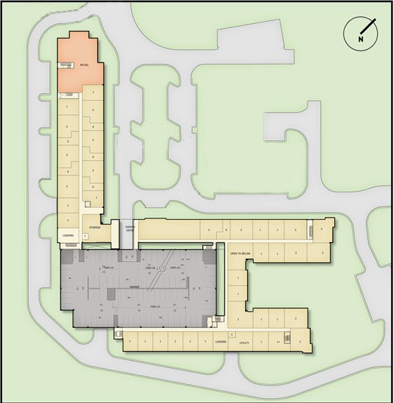
Figure 1: Site plan of The Residence. Light brown area is The Residence, Red area is the Retail portion of the building, and the grey are is the parking garage.
Building name: The Residences
Location: Anne Arundel County, Maryland
Occupancy: Mix use, Residential /Retail
Size: 300,000 gross s.f.
Height: 5 stories, 60 ft.
Dates of construction: September 2009- February 2011
Cost: $39 Million
Project delivery method: Design-bid-build
Owner:
Sumerset Construction
General Contractor/Developer: Encore Developer
Architect: CE*X, Inc
Structural Engineer: Cates
Engineering, Ltd.
Civil Engineer: Morris Ritchie Associates, Inc.
MEP Engineer: Siegel, Rutherford, Bradstock Ridgway, Inc.
Geotechnical: Geo-Technology Associates, Inc
Landscape Architect: The Faux Group, Inc
Located in Anne Arundel County, Maryland “The Residence” is a new construction apartment and retail building part of the Arundel Preserve Town Center Phase I project (Figure 1). The Residence is a 5 story 300,000 s.f. residential apartment building with 6,000 s.f. retail space surrounding a 5 story precast parking garage. This apartment building houses 242 upscale residential units consisting of studio, one, and two bedroom layouts and two level units. Along with the residential units the building also included a terrace level that contains a clubhouse, health center, and an outside pool. The apartment building structural system is composed of light gage steel shear and bearing wall with HSS columns supporting a Hambro joist at the floors and roof level.
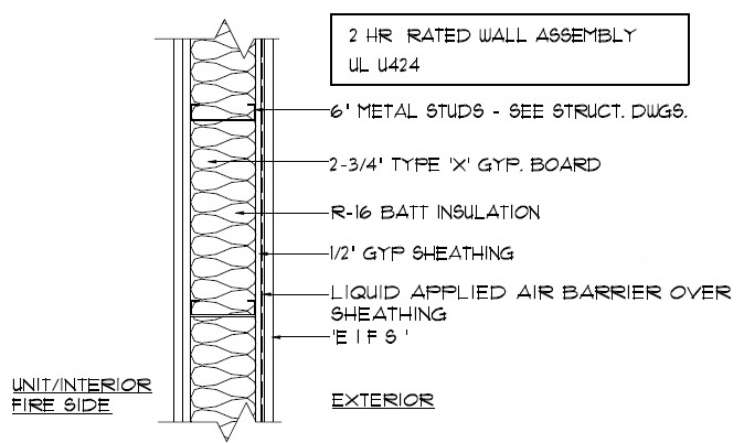
Figure 2a: EIFS Exterior Wall Detail
Click for larger image
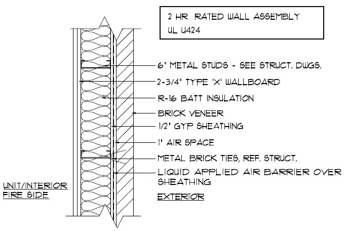
Figure 2b: Brick Exterior Wall Detail
Click for larger image
2003 International Building Code as amended by
Anne Arundel County
2003 International Plumbing Code
2002 NRPA
70 National Electric Code
2003 CABO Model Energy Code, ASHRAE
90.1-1999
2003 International Energy Conservation Code with 2005
Supplement
2006 Fire Prevention Code NFPA 1
2006 Life Safety
Code NFPA 101
Maryland Accessibility Code
Fair Housing Gide
1998
ADAAG 2004
ANSI A1 17.1 2003
Town Center District: designed to encourage mixed-use development of commercial and multifamily residential zones.
Not Applicable
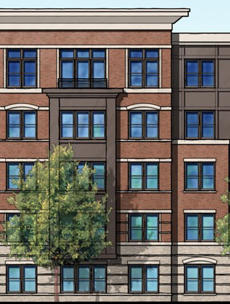
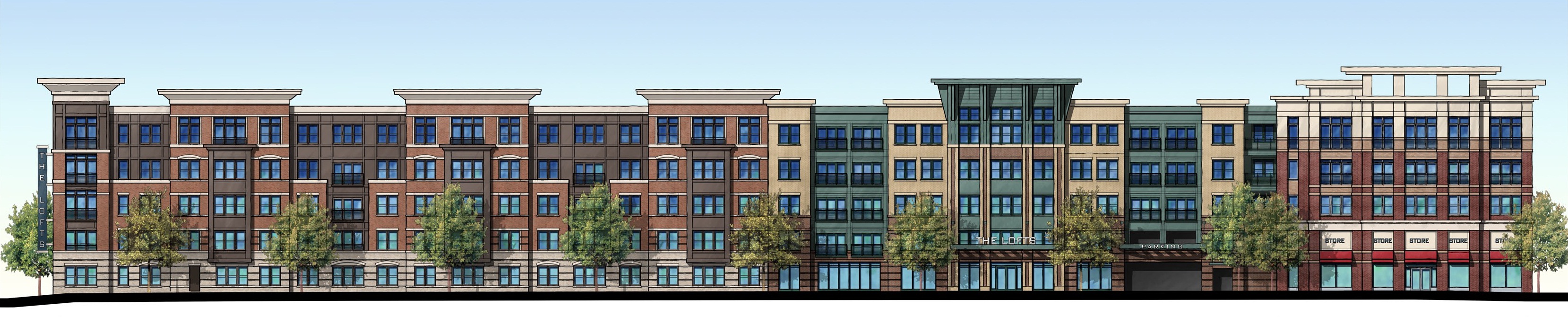
Figure 3:Building Facades
EIFS system (cream color area)
Brick
(red color area).
The design building enclosure for The Residence composes of both brick veneer and Exterior Insulation Finishing System (EIFS). The typical composition of the EIFS consist of at least 3 layers; a foam plastic insulation (extruded polystyrene), a fiberglass reinforcing mesh, and a finish topcoat. The brick veneer façade is composed of face brick veneer with a 1” air space and sheathing, all attaches to 6” metal studs (Figure 2). The buildings envelop uses both of the façade systems with the EIFS primarily located at the top and bottom of the building with the brick façade located in the middle (Figure 3).
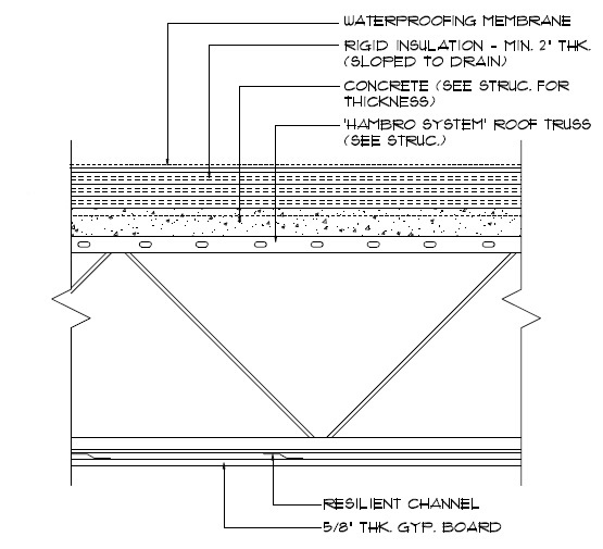
Figure 4: Roof Detail
Click for larger image
The roofing of The Residence uses a single-ply EPDM (ethylene propylene diene Monomer) membrane covering rigid insulation. Extruded polystyrene rigid insulation with a minimal thickness of 2” is the primary insulation used in the roofing system and is sloped to roof drains to prevent water problems. The membrane and rigid insulation is positioned on top of 2-3/4” concrete slab which is than supported by a ‘Hambro’ system roof truss giving the system a 2-hr fire rating (Figure 4).
At this time The Residence has no predominate sustainability feature that was used in design of the building. However since this a multifamily residence sustainability may not have been a consideration.
The Residence houses four roof top dual-coil air handling units, two at 6,000 CFM and two at 7,000 CFM, which are used to serve the corridors of all floor. There are four addition dual-coil air handling units ranging from 1,100-3,000 CMF and they serve all of the public areas of the building. Each of the apartment houses its own concealed modular type dual-coil vertical fan coil ranging from 300-1,200 CMF. The cold water is supplied by three 290 tons capacity centrifugal chiller units each are attached to a 290 tons capacity forced draft cooling tower located on the roof. The hot water is supplied by three natural gas hot water boilers with an output of 3520 MBH (1,000 Btu/hour).
Electricity to the building is provided by two 277/480v 3 phase 4 wire transformers, one for residential power and one for commercial power. A 2,000A main lugs only main switchboard, located in the south east corner of the building, is used for the commercial power which power three 800A main lugs only 277/480v 3 Phase 4 wire distribution panels. A 4,000A main lugs only main switchboard, located in the north east corner of the building, is used for the residential power which powers a second 2,000A main lugs only main switchboard and a 400A 277/480v 3phase 4 wire distribution panel, used only for the elevators. The second residential 2,000A switchboard powers two distribution substation both housing a 750KVA 480V Δ – 120/207v Y dry type transformer, which than powers 16 800A. There is one emergency generator capable of producing 750kw at 80% power factor, 277/480v 3 phase, connected to four automatic transfer switch for emergency power.
The residence primarily utilizes fluorescents and compact fluorescents throughout the build but also used incandescent, LED, and metal halide luminaires. The building employs 120v, 277v, and low voltage (12v) systems for the lighting. The use of T5 and T8 lamps are used throughout the building.
According to the geotechnical report the building rest on Silt-Clay Facies which is identified as clay, silt, and subordinate fine to medium grained muddy sand. The ground water table was located to be at min 24 feet below existing grade which is well below the foundation of the building. From the report it was determined that the structures can be supported on shallow spread footings with an allowable bearing pressure of 5,000 pounds per square foot.
The building foundation system uses a 3’-0” wide strip footing with 3’-0”x3’-0” to 15’-0”x15’-0” column footing pads located manly around the retail space and clubhouse area. The slab on grade was design to be 4” thick reinforced with 6 x 6 W1.4 xW1.4 welded wire fabric. All foundation concrete was to be a 3,000 psi at 28 day strength.
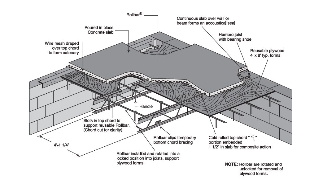
Figure 5: Hambro floor system
Click for larger image
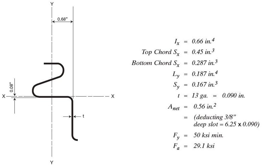
Figure 6: Top cord of the Hambro bar joist
Click for larger image
The Floor system that was used for the Residence was the Hambro floor joist flooring system. The Hambro floor system uses a spicily design steel bar joist with a “s” shape top compression cord which serves three functions in the system, a compression member in the non-composite joist during the construction stage, a chair for the welded wire fabric, and it becomes a continuous shear connection for the composite stage. Detail information of the “s” shape top cord can be seen in figure 6. The floor slab is a 3” thick 3,000psi concrete with 6 x 6 W2.9 x W2.9 welded wire fabric, this particular floor thinness was pick to give the system a 2 hours system. The slab is than supported by a 20” deep Hambro bar joist.
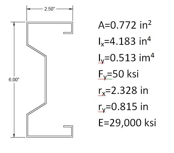
Figure 7: Light gage stud
Click for larger image
The design framing system used in the Residence was a light gage steel load bearing walls which is used to support the Hambro floor system and gravity loads in the build. The particular system that was used in the construction of the build was the SigmaStud® load bearing light gage steel stud which is a product of The Steel Network Company. The stud design is engineered to have a significant increase in load capacity when compared to the conventional “C” shaped studs. The Residence uses a 6” wide 18 gage stud with a flange length of 2.5”, See figure 7 for detail information of stud used for the building. The exterior wall and interior corridor walls of the Residence are primarily the bearing walls in the building.

Figure 8: Light gage Shear wall framing
Click for larger image
The lateral system used in the Residence was a light gage shear wall system design and engineered by The Steel Network Company. The system utilizes light gage 50 ksi steel hot dipped galvanized coated straps on both sides of the wall for shear resistance. A 6” wide flat strap was used in lateral system of the Residence. See figure 8 for a simple framing detail. The shear walls are located all throughout the build, with most of the shear wall located in the corridors walls and the walls separating the apartment.
The Residence is equipped with fire alarm system combination audible and visual device located throughout the building. The build does not have an automatic sprinkler system. All external and internal bearing wall and unit separation wall will have a minimum fire rating of 2 hours. All structural framing members, including the floor system, will also have a minimum fire rating of 2 hours. Each start well has a 6” stand pipe with a 2 ½” fire department valve.
Transportation throughout the Residence is facilitated through four staircases and three elevators. The staircases are located in the end of each wing of the building with one staircase in the center. The elevators are spread out equally throughout the building.