|
||||||||||
| BUILDING STATISTICS | THESIS ABSTRACT | TECHNICAL ASSIGNMENTS | THESIS RESEARCH | THESIS PROPOSAL | PRESENTATION | FINAL REPORT | REFLECTION | E-STUDIO | ||
|
BUILDING STATISTICS PART I |
|||||||||||||||||||||||||||||||||||||
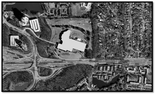
Fig. 1 | Site Map of 7700 Arlington Blvd.
|
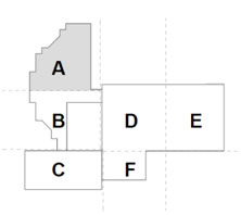
A/B is called the Northwest Building | 4 stories above grade Fig. 2 | Bldg. Key Plan & Description
|
||||||||||||||||||||||||||||||||||||
|
|||||||||||||||||||||||||||||||||||||
|
|||||||||||||||||||||||||||||||||||||
|
|||||||||||||||||||||||||||||||||||||
Architecture |
|||||||||||||||||||||||||||||||||||||
Design and Functional Components |
|||||||||||||||||||||||||||||||||||||
7700 Arlington Boulevard is comprised of three buildings with a four story atrium in the middle and will be the new home to the Defense Health Headquarters (DHHQ). The three buildings were originally built between the 1950s to the 1980s. The unique engineering and architectural quality is that even though the three buildings differ in one way or another they still function as one whole building. Refer to the building key plan and description for building name clarification. The Northwest Building is four stories tall with a height of 47 feet and a gross square footage of 267,436 SF. The Southwest Building is four stories tall with a height of 43 feet 10 inches and a gross square footage of 159,005 SF. The Main Building is two stories tall with a height of 31 feet 10 inches and a gross square footage of 258,209 SF. Overall the architecture of 7700 Arlington Boulevard looks like a pretty typical office building. One key feature includes the glazed aluminum curtain wall that is blast proof around the entire building. Since this structure was pre-existing, the overall scope of work includes all of the following:
|
|||||||||||||||||||||||||||||||||||||
|
|||||||||||||||||||||||||||||||||||||
Zoning Requirements |
|||||||||||||||||||||||||||||||||||||
Fairfax County, Zone I-3 - Light Intensity Industrial District Lot Size Requirements:
|
|||||||||||||||||||||||||||||||||||||
Historical Requirements |
|||||||||||||||||||||||||||||||||||||
Even though there is a good deal of history with 7700 Arlington Blvd. because it was built between the 1950s to the 1980s there are no historical requirements.
|
|||||||||||||||||||||||||||||||||||||
Building Enclosure |
|||||||||||||||||||||||||||||||||||||
Building Facades |
|||||||||||||||||||||||||||||||||||||
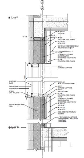
In Figure 3 a typical exterior wall and window are shown as well as a typical parapet section. The exterior façade is made up of the curtain wall, precast panels, brick, and glass. The glazed aluminum curtain wall is sealed with silicone in order to meet the performance requirements. Also, the exterior windows are comprised of blast resistant glass which is made up of the following materials:
|
|
|
|||||||||||||||||||||||||||||||||||
Roofing Membrane |
|||||||||||||||||||||||||||||||||||||
For segments A/B a full roof tear-off needs to be completed and will be replaced with a hot fluid applied roofing system. The existing roofing membrane used for segments C/D/E/F will be used in this renovation. There is a partial re-roofing in these segments which also consists of a hot fluid applied roofing system. Listed below is the makeup of the existing roof for segments C/D/E/F. Segment C is as follows: Segment D/E/F is as follows:
|
|||||||||||||||||||||||||||||||||||||
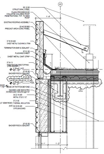
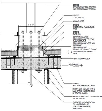
The hot fluid applied roofing system is made up of the following (Refer to Figure 4):
|
Photo courtesy of James G. Davis Construction Corportation Fig. 4 | Section Detail at Segment B Roof Penetration |
||||||||||||||||||||||||||||||||||||
Sustainability Features |
|||||||||||||||||||||||||||||||||||||
7700 Arlington Blvd. will feature a vegetation roof in certain areas of the roof for the building. The HVAC system will be protected in order to ensure good filtration as well as certain materials will be used during construction like sealants or caulks. Another LEED aspect will be scheduling certain finishes together in order to reduce the absorption of VOCs by absorptive materials. A few more items that help with LEED points are housekeeping, pathway interruption, and monitoring which includes progress photos. The base building will not qualify for any LEED certifications, but the tenant side will meet LEED silver certification since the tenants are a branch of the government.
|
|||||||||||||||||||||||||||||||||||||
BUILDING STATISTICS PART II |
|||||||||||||||||||||||||||||||||||||
Construction |
|||||||||||||||||||||||||||||||||||||
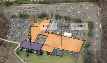
The project was awarded to Davis on July 12, 2010 after about six months of evaluating the SFO responses. SFO stands for solicitation from offer which is where an agency, in this case DHHQ, posts all their requirements for a space they would like to occupy. It is a public posting where different property owners will send in a bid that attempts to meet their requirements and costs. Three months later Davis was able to mobilize on the construction site. GBA Associates Limited Partnership is the owner responsible for the new 7700 Arlington Blvd. site. DHHQ (Defense Health Headquarters) is going to be the tenants of this new space. The reason they are building this facility is because the Defense Base Closure and Realignment Commission (BRAC) recommended that the Department of Defense relocate all facilities to be in accordance with BRAC BP 198. BRAC BP 198 is where a bunch of government buildings must be realigned in order to support certain threats. For example, 7700 Arlington Blvd. will have a blast proof façade, a progressive collapse system and more in order to comply with the BRAC Commission’s recommendations.
The project delivery system for 7700 Arlington Blvd. is Design-Bid-Build. The contract type for the general contractor services with Davis is a Guaranteed Maximum Price. Due to the complexity of the project there had to be constant communication between every player on the job. There was a lot of research done to find out what the existing conditions were during the design phase of construction. Raytheon’s high security did not allow for any onsite research which proved to force more communication and coordination amongst all trades. In this case, most of the subcontractors like the glass and glazing contractor were considered to be design-assist due to the tightness of the construction schedule and how much information was necessary to design something new on an existing structure.
|
Photo courtesy of James G. Davis Construction Corportation Fig. 5 | 2-phase Construction Sequence
|
||||||||||||||||||||||||||||||||||||
Demolition |
|||||||||||||||||||||||||||||||||||||
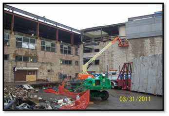
Since 7700 Arlington Blvd. is an already existing structure, there will be certain systems demolished for this project. The main materials that will be demolished include the removal of the building façade, louvers & windows, elevator structure, interior stairs, existing penthouse structure, cafeteria, antenna room, and the existing parapet for the entire perimeter of the Main building which is shown in the picture to the right. In addition to these materials being removed, two mechanical systems will be removed, the entire electrical & lighting system, and the plumbing and fire protection systems will be demolished. The initial demolition includes the removal of asbestos and lead-based paint and lead-containing components. Removal of HVAC duct insulation, cementitious panels, textured ceiling material, boiler exhaust duct, elevator doors, and many other pieces will be removed due to asbestos from the premises in order to ensure a safe work environment. If any lead-based paint and/or lead-containing components are found they will be removed to OSHA regulations. Areas that could contain lead include electrical conduit, structural I-beams and columns, glazed ceramic wall tiles, interior door lintels, freight elevator doors, and more materials. There are a few selective structural elements that need to be demolished. The existing fourth floor exterior wall assembly in the Northwest and Southwest buildings, along with the Northwest building roof assembly to the surface of the structural substrate will be removed. All interior partitions and associated doors and frames will need to be demolished unless otherwise noted on drawings. Other items that will be demolished include all existing ceilings and all floor finishes.
|
Photo courtesy of James G. Davis Construction Corportation Fig. 6 | Demolition of Existing Parapet for Perimeter of Main Building |
||||||||||||||||||||||||||||||||||||
Structural Steel Frame |
|||||||||||||||||||||||||||||||||||||
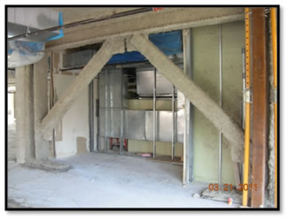
Since this is an existing structure and each building was built at separate times the structural system in each building varies. The main building structural system is primarily composed of concrete. The structural steel in the main building includes steel columns that extend up from the upper level slab and support a steel beam and girder framed roof. The cafeteria roof framing will be demolished and replaced with a new steel frame and gypsum roof similar to the already existing roof. A steel framed roof is the primary structural system in the Southwest building. There are steel pile sections that extend from the fourth floor to the roof. The roof consists of a metal deck on bar joists and steel girders. The roof live load capacity is limited to 30 psf and is not able to accommodate concentrated loads. Lastly, there is no prominent existing structural steel within the Northwest building. In the renovation, different structural systems will be installed to help support the structure if every under certain threats. A progressive collapse system will be implemented around the perimeter of the Northwest and the Southwest building. This system consists of W24x103 steel beams with varying W24x103 and W24x131 kickers. Kickers are used to support the progressive collapse system. The steel columns that run from the roof to the foundation include eight different types of HSS columns. Seismic bracing enhancement is another part of the structural system that was renovated. In the Northwest building HSS 8x8x3/8 braced frames were used to support the structure while in the Southwest building HSS 6x6x61/4 and HSS 6x6x3/8 braced frames were used. HSS 6x6x3/8 and HSS7x7x3/8 were the primary seismic bracing for the Main building.
|
Photo courtesy of James G. Davis Construction Corportation Fig. 7 | Installed Seismic Bracing |
||||||||||||||||||||||||||||||||||||
Cast in Place Concrete |
|||||||||||||||||||||||||||||||||||||
Concrete spread footings with concrete basement walls and concrete flat slabs at the upper floor level are used in the Main building. The columns have capitals and drop panels that extend out approximately 1/6 of the adjacent span dimension from the column centerlines. For the Southwest building, the foundations are spread footings that occur in a crawl space beneath the ground floor. All the floors are cast in place concrete two-way flat slabs and have beams at the building perimeter. All floors including the ground level are designed to support 100 psf. The majority of the Northwest building is founded on spread footings, with a portion of the building including the lobby atrium area supported on a mat foundation. The ground floor level consists of a 6” concrete slab on grade, which should be capable of supporting larger uniform loads. The 2nd through 4th floors and the roof are all framed with two-way flat slabs and drop panels at the columns. The slabs are design for 125 psf, at the floors, and 30 psf at the roof. There is no major cast in place concrete activities being performed on this job since no slabs or structural systems will be demoed. Minor concrete work will need to be done if existing holes in the slab need to be filled.
|
|||||||||||||||||||||||||||||||||||||
Mechanical System |
|||||||||||||||||||||||||||||||||||||
The mechanical system is designed to satisfy the requirements of meeting LEED CI Silver certification as well as provide the appropriate level of comfort for the future tenants of the building. There are three basic air conditioning systems throughout all the buildings with the first system being an all-air rooftop cooling system that distributes air to different spaces through low-pressure ductwork and ceiling diffusers. The return air will be sent back to central duct risers which are through a ceiling plenum. The second system is a closed-loop water source heat pump system. There are interior and perimeter zones for this system with the interior zone having large heat pump air-handling units in mechanical rooms on each floor. The perimeter zone has individual heat pump units located in each office along the perimeter. A roof top unit is home to the closed-loop hydronic circulation system where it houses pumps, boilers, and cooling towers. The third system is a chilled water/hot water system with central VAV air handling units. Low-pressure ductwork and ceiling diffusers will be used again to distribute the air throughout the building. Increased ventilation is provided for each system type by roof mounted preconditioning outside air units or by integrated heat wheels. A direct digital control system will be used to monitor and control the three HVAC systems. There are two types of fire suppression systems that will be used throughout each building and they are a wet-pipe sprinkler system and a dry-pipe sprinkler system.
|
|||||||||||||||||||||||||||||||||||||
Electrical System |
|||||||||||||||||||||||||||||||||||||
The electrical system for all three buildings will consist of a 480/277V, 3-phase, 4-wire, 4000A system. A 15000kVA pad-mounted outdoors transformer that belongs to the electric utility company is also incorporated into the buildings’ electrical system. Three generators will help back-up the electricity for this project.
|
|||||||||||||||||||||||||||||||||||||
Masonry |
|||||||||||||||||||||||||||||||||||||
The typical CMU non-bearing wall with steel or precast lintels varies in size based on wall thicknesses as well as different pressures. The masonry blocks will be placed behind the facade system in order to help support it. The only area that will need scaffolding is in the open atrium.
|
|||||||||||||||||||||||||||||||||||||
Curtain Wall |
|||||||||||||||||||||||||||||||||||||
A glazed aluminum curtain wall will be used on the front entrance to ensure performance and aesthetics. The curtain wall will be placed on the Northwest building where the main entrance is only two stories tall.
|
|||||||||||||||||||||||||||||||||||||
| Senior Thesis Main Page | Penn State | AE Department | AE Computer Labs | Contact |
| This page was last updated on 1/17/2011, by Christie Smith and is hosted by the AE Department Copyright 2011 | ||||
| Note: While great efforts have been taken to provide accurate and complete information on the pages of CPEP, please be aware that the information contained herewith is considered a work-in progress for this thesis project. Modifications and changes related to the original building designs and construction methodologies for this senior thesis project are solely the interpretation of Christie Smith. Changes and discrepancies in no way imply that the original design contained errors or was flawed. Differing assumptions, code references, requirements, and methodologies have been incorporated into this thesis project; therefore, investigation results may vary from the original design. | ||||