Seneca Allegany Casino/Hotel Addition
Salamanca, NY
Nicholas Reed
Structural Option
Welcome to Nicholas Reed's AE Senior Thesis Website
Nicholas Reed
|
|
||||||||||
|---|---|---|---|---|---|---|---|---|---|---|---|
Welcome to Nicholas Reed's AE Senior Thesis Website |
|||||||||||
The Capstone Project Electronic Portfolio (CPEP) is a web‐based project and information center. It contains material produced for a year‐long Senior Thesis class. Its purpose, in addition to providing central storage of individual assignments, is to foster communication and collaboration between student, faculty consultant, course instructors, and industry consultants. This website is dedicated to the research and analysis conducted via guidelines provided by the Department of Architectural Engineering. For an explanation of this capstone design course and its requirements click here.
|
Building Statistics
Building Codes Building codes used in the most recent addition include the 2010 New York State building code, based on the 2006 IBC and 2005 ASCE-7, with specific changes for New York State such as snow and seismic conditions. Project Team
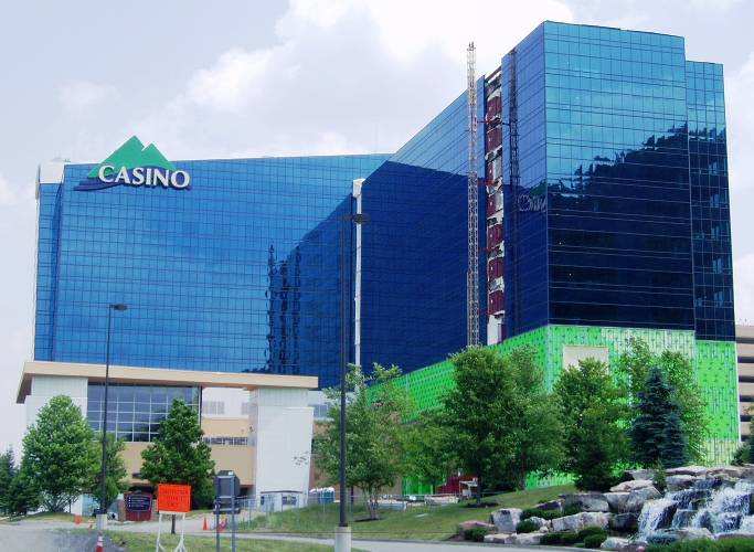
Dates of Construction Architecture The hotel addition is shown on the right of the above image. The main structure is entirely comprised of steel beams and columns, with concrete slabs on grade on each floor and roof level. The perimeter long direction is comprised of rigid moment frames, while the short direction is comprised of interior diagonal braced frames. The entire structure is supported by steel pile foundations driven to bedrock. The lower 3 levels (shown by the green insulation) consist of larger assembly areas, game rooms and cafeterias, with the ground level used for transportation of goods and a mechanical room. A service elevator that was already in the existing building connects to the ground floor of the addition.
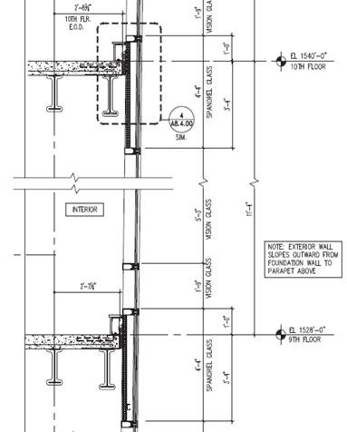
The façade of the Hotel Addition consists of 2 parts, with insulated tempered glass covering the majority of the building where the rooms and penthouse suites are located. The lower 3 levels are sheathed in metal panels. Shown below is an exterior wall section for the 9th floor. The darker sections of glass shown in the top left are where the rooms are located, shown in section as the vision glass. The spandrel glass is backed by metal studs. Interior curtain walls are also framed by metal studs. More detailed information of sustainability features has been requested, meanwhile, it is known that there are operable louvers to control the amount of daylight, and the wealth of glazing on a majority of the façade allows for plenty of natural light.
Structural Foundation Framing Lateral Roof Mechanical A Variable Air Volume (VAV) system is used in the SAC Hotel Addition. The existing hotel tower houses a mechanical room on the 3rd floor that feeds into the new addition. This mechanical room has 3 AHUs, boilers, and water pumps. There is one AHU located on the roof. Since the hotel has a repetitive floor plan, the location of restrooms is consistent per floor, allowing for plumbing to stay in condensed locations as it moves up the building. Fire Protection The SAC Hotel Addition is mostly comprised of steel, thus spray fireproofing is required. Fireproofing is applied to all columns, beams and the underside of the metal deck with a 2 hour rating. A sprinkler system services each room and corridor per floor. Lighting/Electrical The new addition is powered by a 480/277V 3 phase electrical system for a majority of the building with receptacles and light fixtures on a 208/120V 3 phase system. The 3rd floor mechanical room houses 2 transformers, each serving panelboards located on staggered floors the whole height of the builiding. Lighting fixtures include CFLs, LEDs, and fluorescents. Transportation The existing hotel tower was built with an elevator shaft housing 3 elevators. The new hotel addition is tied to the existing addition with an expansion joint. At this expansion joint, the new addition's corridor connects to the existing tower with the demolition of a hotel room and a curtain wall. At the other end of the new addition is a stair tower that services the entire building.
(Photos courtesy of Jim Boje, PE (Wendel) and drawing, JCJ Architecture) |
Note: While great efforts have been taken to provide accurate and complete information on the pages of CPEP, please be aware that the information contained herewith is considered a work‐inprogress for this thesis project. Modifications and changes related to the original building designs and construction methodologies for this senior thesis project are solely the interpretation of Nicholas Reed. Changes and discrepancies in no way imply that the original design contained errors or was flawed. Differing assumptions, code references, requirements, and methodologies have been incorporated into this thesis project; therefore, investigation results may vary from the original design.
This page was last updated on 1/11/2013 by Nick Reed and is hosted by the AE Department ©2012-2013