Building Statistics
- Part 1 -
General Building Data
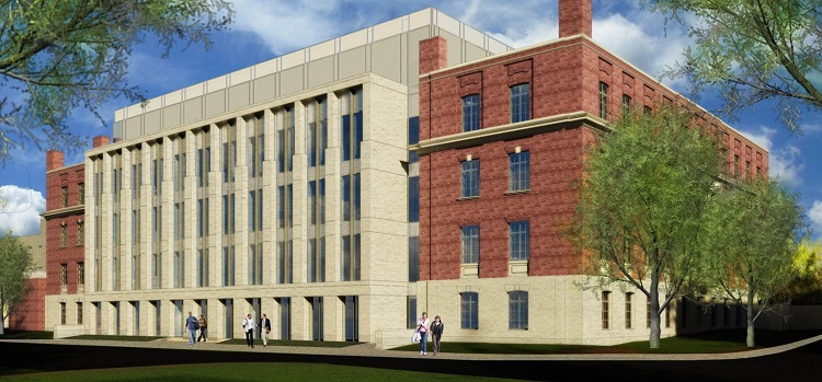
Building name: Steidle Building
Construction Type: Addition and Renovation
Location and site: Pennsylvania State University, University Park, PA
Building Occupant Name: Materials Science and Engineering Department,
.......................................... College of Earth and Mineral Sciences,
........................................... The Pennsylvania State University
Occupancy types: Mixed - Classroom, Laboratory, and Office
Total Size: 100,000 Sq. Ft.
Renovation: 65,000 Sq. Ft.
New Construction: 35,000 Sq. Ft.
Number of stories: 5 Floors above grade
Dates of construction: June 2014 - June 2016
Overall Project Cost: $52 million
Project Delivery Method: CM At Risk
Contract Type: Guaranteed Maximum Price
Primary Project Team
Owner: The Pennsylvania State University
.
Construction Manager: Mascaro Construction Co., LP
Architects: EYP Architecture and Engineering

Civil Engineering Consultants: Pennoni Associates Inc.

Structural Engineering Consultants: Keast and Hood

Mascaro logo provided by the company
All other logos can found at their respective websites
Architecture
The original Steidle Building was built in 1929 under the direction of the former dean of the College of Mineral Industries, Edward Steidle. The building needed to accommodate the growing college with new lab and facility spaces. Charles Klauder, architect for previous Penn State projects like Henderson, Sackett and Old Main, was selected to design the new building. His plan boasted a classical, Beaux-Arts design style with a distinctive rotunda and portico, as seen below in Figure 1.
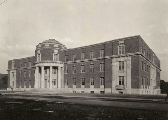
Figure 1: The Steidle Building as photographed back in 1929. The main feature of the building is its rotunda and
portico
centered
between the two wings of the building.
Although the building has undergone many updates, a major renovation hasn’t occurred since 1940 when a central wing was added to house additional lab space. The main focus this project’s design is to rebuild the central wing primarily as classroom space on the first and open lab spaces on the second through fourth floors. Renovations are also being made to the original building to include specialized labs on the first floor and office space on the second through fourth floors. Additionally, a open floor-to-ceiling atrium is being built in between the north side of the new central wing and the south side of the existing building. Finally, a fifth-floor penthouse has been added to house the new HVAC and plumbing systems.
Source: http://www.matse.psu.edu/steidle/history/index.html
Codes
International Building Code 2006
Uniform Construction Code 2009, per Penn State's L&I requirements
Zoning
According to the College Township Code Chapter 188, Penn State is designated as a University Planned District, which is “ intended to provide a single zoning mechanism which can accommodate the university's missions of education, research and public service.” The Steidle Building is located within Subdistrict 5, which constitutes the central area of University Park except for Pattee Mall and Old Main Lawn.
Source: http://ecode360.com/10704992
Historical Requirements
This project focuses on keeping as much of the original 1929 building as possible. Special considerations have been given to protecting the brick veneer and interior structure as the new central wing is integrated into the building. Some building elements, like the existing windows and rotunda roof, had to be replaced
Building Enclosure & Roofing
Most of the building enclosure is the original brick veneer walls constructed in 1929. However, the south face of the central wing features a new glass curtain wall supported by limestone-cladded columns. The fifth floor penthouse features an exterior metal panel wall system supported by moisture-resistant gypsum wallboard sheathing, air and vapor barriers, and rigid insulation. An aluminum-frame skylight covers the top of the interior atrium to allow natural light to enter the central areas of the building. Both the existing building and the central wing utilize a highly reflective thermoplastic polyolefin (TPO) roofing system supported by rigid insulation on steel decking. Refer to Figure 2 (below) for details.
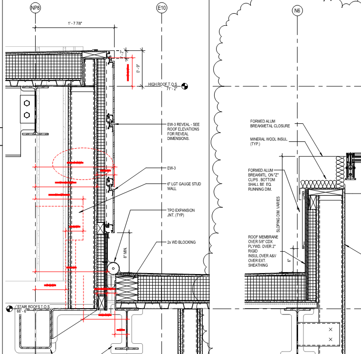
Figure 2: Roof Wall Details at the roof wells (at left) and at the atrium skylight (at right). The sections show the composition of the aluminum metal panel wall system and the TPO roofing system. These details are typical for the vast majority of the penthouse.
Sustainability Features
This project has applied for a LEED certification with an end goal of a LEED Silver Rating. Due to the nature of the renovation, sustainable design options were limited to natural lighting, solar reflectance, and HVAC system commissioning. Many of the sustainable site credits were already present due to the building’s location on campus. The biggest focus for sustainability is on utilizing materials that were regionally produced, were manufactured with recycled content, and/or were created with low VOC content.
Construction Details
The project is split into three phases. The first phase is focused on the demolition of the existing central wing that was originally constructed in 1940. Also occurring during this phase is the gutting of the interior of the existing building that is to remain. This includes demolishing the existing stair towers as well as sections of the existing southwest and southeast wings to make room for the new stair towers. The second phase is focused on the erection of the concrete structure for the central wing. The phase starts with installing the micropile foundation and slab-on-grade that support the rest of the columns and slabs. Also during this phase, interior work starts in the existing building. This includes the ductwork, piping, plumbing and metal stud walls. The third phase is focused on exterior work, including installing the limestone facade on the south of the central wing and touching up the brick on the existing building.
Every day on the site starts with the Plan of the Day (POD) meeting. This is when the trades gather together to discuss who will be working where in the building and on what activities. The trades will also coordinate and plan around any potential conflicts that might arise, i.e. who needs to use the crane to get materials in the building. Finally, before heading off to work, the trades will partake in their morning stretches in order to prevent potential strains or injuries that could come from not being limber enough for the chosen work.
Structural Systems
The structural system substantially differs between the existing building and the new central wing. The structural system for the existing building utilizes steel beams supporting concrete decks for the interior frame and load-bearing masonry walls for the exterior system. The roof is supported by a network of steel trusses for the east and west wings and long-span steel girders for the north side of the building.
On the other hand, the new central wing expansion primarily utilizes a concrete structural system with various subsystems used throughout. The second floor deck utilizes post-tensioned beams that run along the column lines through the 80 seat classroom and the computer learning lab. These beams support the columns above the classrooms that do not extend all the way down to the building’s foundation. The third and fourth floor decks comprise of a flat plate concrete slab system to support the lab spaces above. The only item of note for these slabs is that there is additional reinforcement around the two mechanical shaft openings in each slab. This helps to prevent localized deformations in the slab for these semi-cantilevered areas. The fifth floor slab utilizes a one-way concrete slab system with girders running between them at approximately 10’-3” OC.
The penthouse itself does not use a concrete system, but rather employs a steel framing system to support its enclosure. Of particular note are the roof wells where the exhaust fans for the EAHU’s reside, as well as the exhausts for the fume hoods in the laboratories. Due to the fact that space would be limited in this area once the AHU’s and EAHU’s were installed, special coordination considerations had to be made for the steel in this area.
Mechanical Systems
The HVAC system for this building is a 100% Outside Air system. It’s main pieces of equipment are the two 70,000 CFM Air Handling Units (AHU’s) and the two 65,000 CFM Exhaust AHU’s (EAHU’s). These AHU’s facilitate heating and cooling throughout the building through a variety of reheat coils (RHC’s), fan coil units (FCU’s), and variable air volume boxes (VAV’s). The reheat coils only provide heating to the supply air whereas the fan coil units and terminal boxes provide both heating and cooling. Furthermore, the fan coil unit recycle air in the office spaces as a means to lessen the total heating and cooling loads.
The two EAHU’s primarily service the lab spaces, where research often produces contaminants as experimental byproducts that need to be exhausted from the space. This system uses branch lines with sound attenuators and dedicated exhaust VAV boxes. Each of these lines are either used for general ventilation and air flow or for localized extraction (e.g. fume hood hook-ups). It also utilizes a Heat Recovery Unit in order to provide additional heating to the outside air before it reaches the AHU’s. This helps to cut the demand on the AHU’s and its subsequent equipment, leading to smaller and less expensive units than originally needed.
Plumbing Systems
The bulk of the plumbing system, including the heat exchangers, mechanical system pumps, domestic water heaters, and glycol heating systems are located in the mechanical wing just to the west of the main building. This area is being completely gutted as part of the renovation so that brand new equipment that can handle the increased building demands may be installed. It is in this area that the steam line from Penn State’s combined heat and power plant connects to the building to provide low-pressure steam for heating.
Lighting / Electrical
The building houses a 4000 Amp Main-Tie-Main Switchgear that receives electricity from the aforementioned combined heat and power plant and distributes it to the entire building. The system itself is broken down into three distinct subsystems. The first is the emergency standby system that powers the emergency lighting and equipment in the event of a power failure. The second is the low-voltage system (120/208V) that powers the receptacles and low-demand equipment of the building. The third is the high power system (277/480V) that powers all of the lighting and high-demand equipment. Panelboards are localized to service specific areas of the building and are serviced from each floors east and west electrical rooms where the conduit risers are located.
Transportation
Part of the architectural design of the open atrium in the center of the building is a glass elevator located in the southwest corner. It operates between all four of the main floors of the building, as well as up to the mechanical penthouse on the fifth floor. This elevator is also very large, with dimensions of 5’-3” X 8’-0” X 8’-0” and a carrying capacity of 4000 pounds. It is sized as such so that it can not only transport people between floors, but also transport the majority of lab equipment that is either being added, relocated or eventually removed.
In addition to the new elevator, two new stair towers needed to be constructed to replace the old stair towers. During the design phase, it was deemed that the old stairs were not conducive to the design intent that MatSE and Penn State wanted. There the stairs were moved to the north ends of the existing southwest and southeast wings. Like the elevators, these stair towers service the five floors of the building.
Special Systems
A unique feature of the exhaust system in the lab spaces is the use of portable exhaust extractors, or PEX devices (see right). These PEX devices are either used for local bench work extraction or are hard-connected to equipment pieces that need dedicated exhaust lines. They were selected for use by MatSE as a means of making the labs more flexible. Since the PEX devices can be easily hooked up to equipment items and just as easily disengaged, it makes it much easier on MatSE when adding, removing or replacing equipment pieces in the future. They also allow for faster cleaning of lab spaces as opposed to constantly using fume hoods or hand-cleaning work areas.
Another unique system being used in the building is the installation of Tectum Direct-Attached Ceiling Panels in the computer learning lab above the perforated metal ceiling tile and grid. These acoustical panels help to reduce the amount of background noise in a given space. This will be especially useful in a computer lab, like the one in this building, where the computers generate enough background noise to make it hard to hear the instructor. This is not unique to building design - what is unique is that Tectum panels are made up of natural wood fibers. This makes them a much more sustainable option by helping to eliminate waste, using renewable resources, and limiting the use of VOC’s.
|
 Jeffrey Duclos