
| HOME |
| ERIK CARLSON |
| BUILDING STATISTICS |
| THESIS ABSTRACT |
| TECHNICAL ASSIGNMENTS |
| THESIS RESEARCH |
| THESIS PROPOSAL |
| PRESENTATION |
| FINAL REPORT |
| REFLECTION |
| E-STUDIO |
User Note:
|
BUILDING STATISTICS
| GENERAL BUILDING DATA | |
| Building Name: | Bridgeside Building II |
| Location and Site: | Pittsburgh Technology Center, Pittsburgh, PA |
| Building Occupant: | No Tenants are currently finalized |
| Building Type: | Lab/Office space |
| Size: | 160,000 sf |
| Number of Stories: | 5 plus a small penthouse |
| Dates of Construction: | November 2007 to December 2008 |
| Cost Information: | Construction Costs total to $18 Million - GMP |
| Project Delivery Method: | Design-Bid-Build |
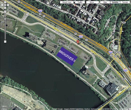 |
| Bridgeside II Site View |
| PROJECT TEAM | |
| Owner: | The Ferchill Group |
| Owner: | The Port of Pittsburgh |
| General Contractor: | Turner Construction |
| Architect: | Strada Architecture, LLC |
| MEP Engineer: | Allen and Shariff Corporation |
| Structural Engineer: | Atlantic Engineering Services |
| Civil Engineer: | Gateway Engineers |
| Geotechnical Engineer: | Professional Service Industries |
| ARCHITECTURE | |
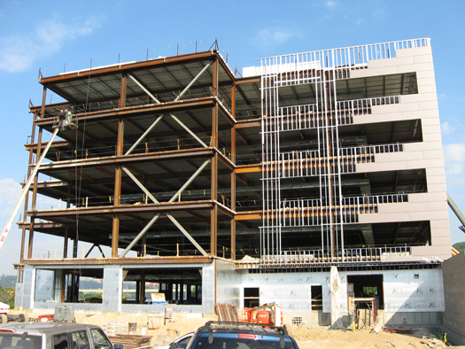
| Architecture: | The Bridgeside II building consists of 5 stories and open floor layouts which will accommodate the needs of the tenants once they are determined. A wet core is located in the center of the building which includes most of the MEP equipment and piping as well as bathrooms on every floor. Bridgeside II is located on the Monongahela River in the Pittsburgh Technology Center which was once the home of J&L Steel Company. To reflect the sites past history the building was given an industrial design with the use of exposed steel framed canopies, screen walls and lateral bracing. Storefront windows and balconies facing the river take advantage of the buildings river front location with views of the Pittsburgh skyline. |
 |
|
| South Elevation showing the Exposed Lateral Bracing | |
| Major Codes: | International Building Code 2006 |
| Zoning: | Commercial |
| Historical Requirements: | There are no historical requirements for the project. However; the building is located on an old steel mill site, owned by J&L Steel, which created unforeseen problems when excavating and drilling mini piles. Many of the old concrete foundations and some steel were buried under the site. |
| Building Envelope: | The building envelope for Bridgeside II consists of three different wall systems. The majority of the envelope consists of insulated metal panels and aluminum storefront windows. Cast stone is located on the lower quarter of the building occasionally running to the top to provide the building with more vertical elements. The storefront windows surround the main entrance and run to the top of the building. They are also located on the river side to provide the building with views of the river and Pittsburgh skyline. The roof consists of a built up roof with an EPDM roof membrane and sits on 1.5”, galvanized roof deck. Surrounding the roof is a steel screen wall which hides the mechanical equipment and enhances the buildings industrial design. |
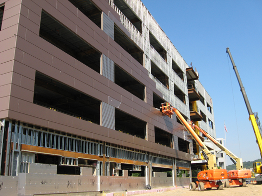 |
| East Elevation showing the Metal Panels being installed |
| BUILDING SYSTEMS | |
| Construction: | The redevelopment of 450 Technology Drive has been a team effort by the Ferchill Group, the Pittsburgh Port Commission and the Urban Redevelopment Authority. Currently there are three projects being worked on at the site which has created a lack of space and also the need for the three contractors to coordinate with each other. Turner Construction is in charge of building Bridgeside II, Allison Park Construction is relocating Technology Drive and Carl Walker has a design-build contact with URA to build a parking garage. Since Bridgeside II is a shell lab and office building, special considerations had to be taken into the design to accommodate either one tenant per floor or multiple. This was handled by creating a central building core and by designing future fume hood shafts to allow for flexible lab space layouts. |
| Structural System: | The structural system for Bridgeside II consists of structural steel and composite steel deck. The framing for floors 2-5 is primarily constructed of W21x44 beams tying into W24x62 girders. The beams have an average span of 32 feet while the girders average span is 30 feet. Lateral bracing is used on each side of the building to compensate for wind loads. The bracing is constructed with hollow steel tube cross bracing. Other than the first floor, which is a slab on grade, each floor has a typical composite deck assembly. It is constructed of 3” normal weight concrete on 3” 20 gage steel deck. Both ¾” shear studs and welds are used to create the composite assembly. The concrete is reinforced with welded wire fabric. The roof framing consists mostly of W18x40 beams, tying into W30x90 girders, and the penthouse framing is constructed with 20K3 joists, tying into W12x14 girders. The composite deck is the same assembly as the lower floors except for where the mechanical units are located. The deck underneath he mechanical units is raised on top of steel channels and is constructed of 3” normal weight concrete on 1” 22 gage steel deck. The building’s foundation consists of H-Piles and concrete pile caps with concrete grade beams around the perimeter of the building. The piles require pre-drilling and must reach bedrock to achieve a bearing capacity of 130 tons. The minimum concrete strength for the foundation elements is 3,000 psi and the interior slabs are 4,000 psi. |
| Mechanical System: | The mechanical system is located outside on the building’s roof surrounded by steel screen walls to shield the units from the public eye. There are 3 roof top units each of which utilizes hot water pre-heat coils and energy recovery wheels. One unit uses 100% outside air and produces 40,000 cfm of supply air. The other two units each use 17,000 cfm of outside air and produce 75,000 cfm of supply air. Bridgeside II also utilizes a boiler, which is located on the roof, and 5 VAV boxes, 1 on each floor. Since Bridgeside II currently does not have a tenant the building is being built as a shell space. Therefore the mechanical system had to be sized based off of assumptions and past projects. The building will accommodate both office and lab spaces. To meet the demands of the future lab spaces each floor was designed for 10,000 cfm of lab exhaust and many wet stacks were added to allow for easy installation of lab sinks. It will be the job of the owner to understand the systems limitations and to take this into consideration when discussing lease arrangements. |
| Electrical System: | Bridgeside II is receiving power from Duquesne Light. The main electrical room is located on the bottom floor along with the generator and back-up generator. There is also an electrical room located in the center core of the building on each floor. The main distribution panel is sized for 4000 amps 480Y/277. Two transformers are located on the first floor and then one on the second, fourth and roof levels. Currently there are only panels designed to feed the mechanical equipment, building core, egress locations and the building’s exterior. Once a tenant moves in there is space for more panels to be installed in the electrical rooms on each of the floors. Similarly to the mechanical system the electrical system had to be designed based off of assumptions. The main service feed was sized for a higher watt per square footage than a typical office building. Also it is assumed that the labs will require a large number of receptacles however there is a large diversity in the amount of usage at any given time. This had to be taken into consideration when sizing the electrical system. The back-up generator is a 1 mega-watt diesel generator which will supply power to life safety systems including the hood exhaust fans. Also the lab equipment will be provided power by the redundancy system. |
| Lighting: | The interior lighting consists of recessed incandescent down lights in the public areas, which are connected to occupancy sensors. Surface mounted fluorescent lights are found in the utility rooms and egress routes. The majority of the interior lighting will be selected by each of the tenants depending on the use of their space. The exterior of the building is contains semi-recessed lights and wall washers. |
| Fire Protection: | Bridgeside II is fully sprinklered with automatic concealed sprinkler heads. This makes spray on fireproofing on the exposed steel unnecessary. However, spray on fireproofing is still required on the elevator and stair well framing. The majority of the sprinklers utilize a wet pipe system except for the loading dock and balcony areas which require a dry pipe system. Since the building is type IIB it must meet NFPA 13 regulations. This means that the maximum sprinkler coverage area is 225 sqft. for office space and 130 sqft. for the rest of the spaces. There is a fire department connection located next to the main entrance and the 6” fire service line enters the building at the South-West corner. The fire alarm control panel is located in the main electrical room and is connected to a 120V emergency power source. Fire alarms, heat detectors and smoke detectors are installed in the finished spaces however more will be required when a tenant fits out the space. |
| Telecommunications: | The telecommunications is being serviced by Comcast and Verizon however the cable won’t be pulled through the building until a tenant has been arranged. The electrical rooms on each floor have 8 4” sleeves stubbed through the floor for future telecomm and data cables. |
| Transportation: | There are three machine room-less Gen2 traction elevators located in the center of the building. Each elevator has a rated capacity of 3,500 pounds and runs at 350 feet per minute. The building also contains two stair cases which have been spaced to accommodate any floor plan configuration. |