Sean Beville Structural TEMECULA MEDICAL CENTER-TEMECULA, CA |
||||||||||||||
WELCOME TO SEAN BEVILLE'S AE SENIOR THESIS e-STUDIO
|
||||||||||||||
|
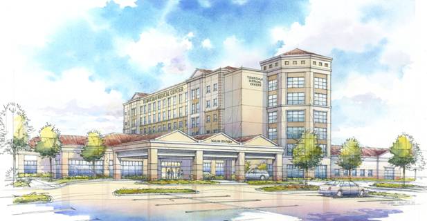
BUILDING STATS GENERAL INFO - PROJECT TEAM - BUILDING DESCRIPTIONS Building Descriptions: Architecture The Temecula Medical Center is designed as a trademark medical facility for the city of Temecula and the surrounding region. It has 6 stories and is approximately 107' tall with it's most predominant feature being the circular tower on the south side. The south tower serves as the main vocal point with large banded windows as well as 4 distinct column points. The exterior facade is made up of mostly portland cement plaster but also features porcelain wall tile (lining parts of the ground level exterior), and pre-finished metal panels (on lower floors).
The roof system of the medical center consists of pre-formed, pre-finished sheet metal coping caps to match the plaster as well as sloped rust colored roof tile. Being located in California, the Temecula Medical Center maintains many architectural motifs originating on the west coast. This style is brought out in the numerous windows on the facade, as well as the rust colored roof. Structural Overview Lateral System Concrete Strengths
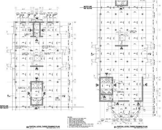
Floor System Topping slabs of the double tees in the D&T consists of 6” normal weight concrete, typically reinforced with #4 at 9” o.c. Typical spans between tee’s is 6’-0 but vary on location. Two-way flat slab reinforcement sizes for the 6-story bed tower vary but are placed equally across designed column and middle strips. A typical floor layout is shown below.
Roof System Foundation Foundations for the shear walls feature footings anchored to the supporting soil by drilled piers, typically being 42” in diameter. Each pier is spirally reinforced, varying in size while the pier caps are typically reinforced with #9 - #11 at 9” o.c. Columns The cast-in-place columns typically run from spread footing through each floor while being reinforced with 12 #9’s vertically and #4 at 6” o.c. horizontally. Pre-cast columns are reinforced with 4 #9’s vertically and #4 at 5” o.c. horizontally. The compressive strength for the C.I.P. columns is 5000 psi and the strength of the PL columns is 6000 psi. . MEP Systems Electrical and Mechanical systems feature standard equipment. Due to limitations, the actual specifications of these systems can not be released.
|
|||||||||||||
senior thesis / the pennsylvania state university / hks inc. / architectural engineering / ae lab / contact sean beville
|
||||||||||||||