General Building Data
- Building name: Crossroads at Westfields Building II
- Location and Site: 4871 Stonecroft Blvd. Chantilly, VA (Parcel 31B1)
- Building occupant name: NA
- Occupancy or function type: Office building
- Number of Stories: 5 stories
- Dates of construction: Project on hold (no tenants) approximately 20 months
- Actual Cost information: Total office base building direct cost (typical core and shell)- $14,542,653
- Project Delivery Method: Design-Bid-Build
Architecture
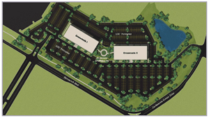
The Crossroads at Westfields are two identical office buildings mirroring each other on site. The site is located in Chantilly, VA in the Westfields development where Lee Road crosses Stonecroft Blvd hence the Crossroads at Westfield. LEED certification was one of the goals for the Building II’s architectural design with the potential to obtain as high as a Gold Rating. The façade of the building is a composite design consisting of precast concrete panels, composite metal panels and an aluminum storefront system.
-
2003 CABO/ANSI A117.1
-
Virginia Uniform Statewide Building code (2003)
-
2003 ICC International Building Code
-
2003 National Electric Code (NFPA 70)
-
2003 International Energy Conservation Code
-
2003 International Fire Code
-
2003 ICC International Mechanical Code
-
2003 ICC International Plumbing Code
- Zoning: I-3 Fairfax County – Westfields development guidelines
- Historical Requirements: NA (new building)
Building Envelope
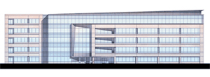
The building envelope has many different types of materials as you circle the building. The North and South façades consist of an aluminum storefront system on the first floor with precast concrete panels and punch windows running up the rest of the façade. The East and West-facing envelopes are the precast concrete panels and aluminum punch windows. The south-facing envelope of the lobby is an aluminum curtain wall system framed out by composite metal paneling.
The roof system consists of EPDM roof membrane on top of 4” of rigid insulation. This sits on steel decking supported by steel joists. Architecturally, there is a composite metal panel parapet sloping up from east to west.
Structural System
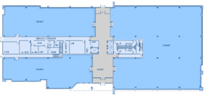
The Foundation system consists of reinforced cast-in-place concrete spread footings. The slab is a 4” thick cast-in-place concrete with 6x6–10/10 welded wire mesh (WWM), ranging in compressive strength from 3000 to 4500 psi. The typical floor consists of 3” 20 gauge composite steel deck with 3-1/4” lightweight concrete slab totaling a total slab thickness of 6-1/4”. The slab shall be reinforced with 6X6-10/10 WWM and have a compressive strength of 3000 psi. A typical bay consists of wide flange beams spaced at 10’ o/c with dimensions of 30’-0” by 41’-8”. The roof is comprised of 1-1/2” 22 gauge Type B wide rib galvanized roof deck, on K series bar joists and steel girders. Laterally, the building is supported by 4 moment frames running in each direction, North-South and East-West.
Electrical System
Building II has a main electrical room located in the southeast corner of the building which is adjacent to the outdoor electrical yard. The yard is fenced off containing a 250 Kw emergency generator and 4 200 VA utility transformers which supply power through 16 4” conduits to the main distribution panels located in the main electric room. From the distribution panels, the buildings electricity which is a 277/480V 3 phase 4-wire system is carried by a 4000A busway to individual transformers on each floor. The transformers step the power down to 120/208V for lighting throughout the building.
Lighting System
The lighting system will be controlled through a lighting relay panel which is located outside the building. It consists of 32 relays and an integrated time clock. The interior lighting consists of mostly fluorescent lighting with the incoming power loads at 120/277A. The corridors contain surface mounted 2x2 parabolic fluorescent lights, while the most of interior contains linear fluorescent lighting. The bathrooms contain recessed downlighting. Also connected to the lighting relay panel is a exterior photocell which will control all of the exterior lighting. When dark, the photocell turns on relays assigned to channels utilizing exterior lighting scenarios.
Mechanical System
Located on the roof of Building II are two Energy Recovery Units with energy wheels each with a capacity of 15,575 CFM supply air and 12,625 CFM exhaust air. The Energy Recover Unit recycle the return air with fresh air and supply the mixed air to individual Self-Contained Units located on each floor per ASHRAE standard 62.1. This system is extremely efficient and providing flexibility to tenants, maximum capacity and easy maintenance. The floor-by-floor self-contained units supply the floors with a 26,300 to 28,725 CFM depending on the floor. Each contains an economizer which is activated if the weather is cold enough saving over 250 net MBH.
Construction
Building II of the Crossroads at Westfields was originally was scheduled to start construction in May of 2008 but is currently on hold. This Design-Bid-Build project is contracted to James G. Davis Construction Corp. of Rockville, Maryland. Once started, the construction process will last about 2 years or 24 months and the total cost will be approximately 14.5 million dollars.
Fire Protection
Building II designed referencing the 2003 IBC Fire Code, classifying the building’s construction as IIB for the fire-resistance-rating. Every floor an automatic sprinkler system per NFPA 13 and controlled by a Fire pump control panel with automatic transfer switch. The alarm system is a low rise addressable system. A Fireproofing spray must be applied to all of the structural members to obtain a 1 hour rating. This includes the structural frame, interior bearing walls, floor construction and roof construction, while the interior non-bearing walls are rated at 0 hours. The shaft enclosures and exit enclosures are rated at 2 hours. Any structural member intersecting a shaft with a 2-hour rating must also be sprayed for a 2-hour rating.
Telecommunications
The Tele-data infrastructure takes advantage of the power throughout the building providing the needs to future tenants. There are four 4” conduits running into the telephone room located on the first floor from the pull boxes outside. Each floor has its own telephone room with ten 5” sleeves for tele-data cables.
Transportation
There are two staircases located within Building II, each located at the end of the “core”. Both staircases top at each floor level while, the east stair case has access to the roof with a ladder and roof hatch. The stair cases are constructed with steel channels and steel pan filled with 2” of concrete. There are three elevators located in the center of the core each with the capability to stop at each floor. The capacity of the elevators are the standard 3500 lbs.
|