| Courtney Glaub: Construction Management 2010-2011 | ||||||||||||||||||||||||||||||||||||||||||||||||
| HOME PAGE | 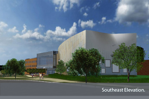 |
|||||||||||||||||||||||||||||||||||||||||||||||
| STUDENT BIO | ||||||||||||||||||||||||||||||||||||||||||||||||
| BUILDING STATISTICS | ||||||||||||||||||||||||||||||||||||||||||||||||
| THESIS ABSTRACT | ||||||||||||||||||||||||||||||||||||||||||||||||
| TECHNICAL ASSIGNMENTS | ||||||||||||||||||||||||||||||||||||||||||||||||
| THESIS RESEARCH | ||||||||||||||||||||||||||||||||||||||||||||||||
| THESIS PROPOSAL | ||||||||||||||||||||||||||||||||||||||||||||||||
| PRESENTATION | ||||||||||||||||||||||||||||||||||||||||||||||||
| FINAL REPORT | ||||||||||||||||||||||||||||||||||||||||||||||||
| REFLECTION | ||||||||||||||||||||||||||||||||||||||||||||||||
| SENIOR THESIS e-STUDIO | ||||||||||||||||||||||||||||||||||||||||||||||||
User Note: While great efforts have been taken to provide accurate and complete information on the pages of CPEP, please be aware that the information contained herewith is considered a work-in-progress for this thesis project. Modifications and changes related to the original building designs and construction methodologies for this senior thesis project are solely the interpretation of Courtney Glaub.Changes and discrepancies in no way imply that the original design contained errors or was flawed. Differing assumptions, code references, requirements and methodologies have been incorporated into this thesis project; therefore, investigation results may vary from the original design. |
Building Statistics: Part 1 | |||||||||||||||||||||||||||||||||||||||||||||||
| General Building Information | ||||||||||||||||||||||||||||||||||||||||||||||||
|
||||||||||||||||||||||||||||||||||||||||||||||||
| Project Team | ||||||||||||||||||||||||||||||||||||||||||||||||
|
||||||||||||||||||||||||||||||||||||||||||||||||
| Architecture | ||||||||||||||||||||||||||||||||||||||||||||||||
The Performing Arts and Humanities Facility (PAHF) will be situated on 4.8 acres on the west side of Hilltop Road, adjacent to the existing Fine Arts, Engineering and ITE Buildings. It will provide new, state-of-the-art facilities for arts and humanities departments and programs. Not only will this facility enhance the teaching, research and public outreach, but it will also heighten the visibility of the arts and humanities as major components of campus and community life. The construction for this new building is designed into two phases, each phase providing different types of space for various departments. Phase one consists of a four story, 90,000sf facility providing a variety of performing arts amenities. The building includes a 275 Seat Proscenium Theater, a 100 Seat Black Box Theater, Scene Shop, Theater Rehearsal Studio, Acting/Directing Studio, Dressing Rooms, Support Spaces, Seminar Rooms, Classrooms, Conference Rooms and Administrative Offices. This phase of the project also includes upgrades to the existing Central Utility Plant and a concrete structure/tunnel connecting the existing Plant Tunnel to the new Performing Arts Facility. An interesting aspect of the PAHF is that it's comprised of multiple structural features. Certain parts of the building are comprised of a steel frame with brick veneer skin. The theaters are built with a concrete framing system with metal panel skin; the transition between theater and classrooms includes a structural masonry block system. Phase two is still in the design process and the projected start date for this portion is not until 2013. This phase will provide space for the Departments of Ancient Studies, Dance, Music and Philosophy.
|
||||||||||||||||||||||||||||||||||||||||||||||||
| Building Enclosure | ||||||||||||||||||||||||||||||||||||||||||||||||
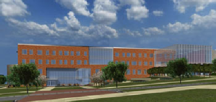
The exterior façade of the building consists of an assortment of materials creating a strong relationship with the current campus buildings. The North elevation, shown in Figure 1, is primarily comprised of brick veneer with certain areas being backed up by CMU. Also shown is a curtain wall system made up of 8" aluminum framing with 1" insulating glass and custom cap covers. The smaller windows encompassed by the brick veneer are aluminum window units with 1" insulating glass. All exterior glass types are 1" insulated glazing units with Low E coating. |
||||||||||||||||||||||||||||||||||||||||||||||||
 |
||||||||||||||||||||||||||||||||||||||||||||||||
| Figure 1 North Elevation | ||||||||||||||||||||||||||||||||||||||||||||||||
The Southeast elevation showing the Proscenium Theater, in Figure 2, is made up of stainless steel wall panels backed up with concrete and steel studs. The remaining building elevations are made of aluminum composite metal wall panels and different types of corrugated metals. |
||||||||||||||||||||||||||||||||||||||||||||||||
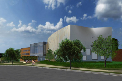 Figure 2 Southeast elevation |
||||||||||||||||||||||||||||||||||||||||||||||||
The roofing system consists of two different types of roofs, a built up roof with tapered rigid insulation and a built up roof without tapered insulation. The tapered roof has a concrete composite deck with a self-adhering vapor retarder. On top of that is the polyisocyanurate tapered insulation covered by a ¼” glass mat faced gypsum cover board. The final exterior membrane is an energy star thermoplastic roofing membrane that is watertight and resists uplift pressures. The difference between the two roof types is that the concrete deck and the vapor retarder are not required under the non-tapered roof; on this roof, the insulation is mechanically fastened to the deck. |
||||||||||||||||||||||||||||||||||||||||||||||||
| Sustainability Features | ||||||||||||||||||||||||||||||||||||||||||||||||
University of Maryland has determined that the project goal is to receive a LEED Silver rating for new construction. This project is expected to be the first building on campus to earn LEED Certification. Some of the LEED credits associated with this project include Pollution Prevention, Alternative Transportation, Waste Management, and Low-Emitting Materials. To reduce the pollution, the construction activities control the soil erosion, waterway sedimentation, and airborne dust generation. Also by using alternative transportation such as bicycles, carpools, and fuel efficient vehicles the pollution and land development impacts can be reduced greatly. A sustainable landscape will be achieved by building atop an existing parking lot and planting grass surrounding the building. For waste management, the project requirement is to divert 50% of construction debris from disposal and the project goal is to use materials with recycled content within 500 miles of the project site. For example, the interior wood products are all FSC (Forest Service Conservation) certified. This project has low water usage by providing low or no flow toilet fixtures. Also installed to this building will be a rainwater harvesting system reusing water for irrigation. Inside the building, low-emitting materials will be used to reduce the quantity of indoor air contaminants that are odorous, irritating and/or harmful to the comfort of the installers and occupants. This is important to have everything controlled in the building by indoor air quality management so that contaminants will not remain in the building. The Low E coating on the glass units reduces radiant heating of the building, thereby decreasing the use of mechanical and electrical equipment to temper the building. The roofing system is comprised of an energy star thermoplastic membrane having a reflective surface. This will also reduce the radiant heating of the interior spaces of the building. An extensive commissioning procedure will be followed at the end of the project to ensure proper functioning of all building elements, and that they meet LEED requirements. |
||||||||||||||||||||||||||||||||||||||||||||||||
| Building Statistics: Part 2 | ||||||||||||||||||||||||||||||||||||||||||||||||
| Primary Engineering Systems | ||||||||||||||||||||||||||||||||||||||||||||||||
Construction: The UMBC Performing Arts & Humanities Facility is located at 1000 Hilltop Circle in Baltimore, MD. The PAHF will be situated on 4.8 acres on the west side of Hilltop Road adjacent to the existing Fine Arts, Engineering and ITE Buildings. This site was previously utilized by the university as a surface parking lot, providing 690 parking spaces for the campus. The new PAHF project, phase one, includes the construction of a new four story, 90,000 GSF performing arts, classroom and office building to house many of the campus’s departments. This phase of the project also includes upgrades to the existing Central Utility Plant and a concrete structure/tunnel connecting the existing Plant Tunnel to the new Performing Arts Facility. There is a separate phase not included in the 90,000SF building, but that phase is still in the design process and is not expected to start until 2013 The largest challenge associated with this project is the complicated relationship between the site excavations, structural excavation, foundations and structural elements. Certain areas are isolated structurally causing a delay in the progress of adjacent work. Another aspect that makes this project difficult is that the structural system is made up of three different systems; concrete, masonry, and steel. The schedule needs to be carefully planned out and evaluated to ensure the highest quality and most efficient project.
|
||||||||||||||||||||||||||||||||||||||||||||||||
Electrical: The electrical system has 15kv medium voltage feeders that come off of the substations. A unit substation consists of two 15kv, 600 amp switches (incoming); one 15kv, 600 amp switch (outgoing); 2500 KVA transformer; and 3200 Amp, 480Y/277 volt, 3 phase, 4 wire, 60 hertz switchgear. Power will be distributed at 480Y/277 volts and dry type transformers will be provided to supply 208Y/120 volt loads. Emergency power will be provided by a natural gas-fired engine generator with a 600KW, 480Y/277 volt, 3 phase, 4 wire set. The facility program required the switchgear to be a double-ended substation, but in the project team meetings, UMBC has decided that a single line up with one transformer is sufficient for this building and a double ended substation is not required.
|
||||||||||||||||||||||||||||||||||||||||||||||||
Lighting: The lighting system illumination levels in the interior spaces will be based on functional category as recommended by IES standards as well as the owner’s lighting requirements and design guidelines. The lighting levels will be based on average maintenance factors of 70% and calculated at the desk top of 30” above finished floor. Most of the lighting fixtures will utilize energy efficient fluorescent T8 and/or T5 lamps and electronic ballasts. Lamps will be rapid start with a correlated color temperature of 4100K and color rendering index of 80. Fluorescent lamp down lights will be provided with high power factor electronic ballasts and compact fluorescent lamps. The lighting fixture selection will be coordinated with the architectural ceiling, and all offices, rest rooms, storages, and other general areas will be provided with 2’x4’ fluorescent lighting fixtures. Dimmable lighting fixtures will be used for special applications, which require dimming. Emergency lighting will be provided in the paths of egress and other critical areas as required to meet the University’s and National Electrical Code requirements. All emergency lighting fixtures and exit lights will be served from the emergency power; no separate emergency lighting fixtures with battery back-ups will be provided. New parking lighting will consist of pole mounted fixtures and security lighting which will consist of exterior wall mounted fixtures. Bollards lighting fixtures will be used for sidewalks and grounding rods will be provided for each pole. All parking, sidewalks, and security lighting will be controlled by a combination of photocells, 7 days/24 hour time clock and a hand-off-automatic switch.
|
||||||||||||||||||||||||||||||||||||||||||||||||
Mechanical: The mechanical rooms are located in the basement level of the new PAHF. A goal of the HVAC systems will be to minimize energy consumption while maintaining space design criteria. Some of the interesting features that contribute to LEED are an automatic shutdown of air handling systems during unoccupied hours subject to building low and high temperature and humidity limits. The controls isolate supply air flow to each floor served from centralized air handling systems based on the floor occupancy schedule. This will be accomplished through DDC system programming, to isolate airflow per floor and per AHU, by closing air terminal unit dampers or floor zone dampers during unoccupied mode. The occupancy sensor controls are reducing the air supply to each space during the day when not in use. There are variable airflow air handling systems with variable frequency controlled fans and variable water flow heating and chilled water distribution systems with variable frequency controls. There is energy recovered from exhaust air and temper outdoor air by the total energy recovery heat wheels. Cooling and dehumidification control for the building will be provided from the campus chilled water distribution system. A pair of 10” chilled water mains are proposed to serve the building. The chilled water system will utilize variable flow pumping within the building via three base-mounted, bronze fitted, end-suction pumps. The campus high temperature hot water system will be utilized as the energy source for heating and domestic hot water generation within the new facility. Preliminary load estimates of design day heating and domestic water requirements for the new facility indicate a peak hourly load of approximately 9100 MBH. The HTHW mains will extend to three shell and tube heat exchangers for low temperature hot water heating service. Chemical water treatment for the HTHW system will be provided at the central plant by UMBC. Humidity will be controlled year around throughout the facility due to its impact on the short term tuning and the long term preservation of musical instruments, and due to the intermittent high occupancy levels which will require the introduction of large amounts of outdoor air. Steam will be generated to humidify the building by point of used gas fired steam humidifiers generally for each AHU located within the building. The facility will be conditioned by fifteen air-handling units, providing each space with their own capacity. The AHU’s airflow quantities will be controlled by VFCs, not inlet vanes or any other control device. Each system will have a dedicated roof mounted spark resistant exhaust fan, corrosion resistant exhaust ductwork, and automatic isolation dampers.
|
||||||||||||||||||||||||||||||||||||||||||||||||
Structural: The complex is composed of a variety of spaces including the three performance spaces, a scene shop, studios, classrooms, offices and support. To respond to the variety of spatial and performance challenges, a composite structural steel frame is recommended. Floor slabs will generally be composed of 2” 20-gage galvanized steel deck plus 3-1/4” of lightweight concrete reinforced with WWF 6x6 x W2.9 X W2.9 creating a 2-hour floor system. The slab will be supported by composite steel beams ranging in depth from 12” at 20’ to 18” at 40’ spans. In general, column spacings have been planned to allow floor beams and girders not to exceed a total structural envelope of 2’-0”. This will expand slightly at some spaces such as the dance studio when a built-up floor with a damping slab and floor vibration criteria may require a slightly deeper structure. There are 6 different roof elevations and many will have roof-top units supported thereon. Roof screen frames are also required. The baseline scheme suggests the use of composite steel construction for all roofs as the concrete is necessary for noise attenuation. Column sizes are generally W10s, although larger columns may be required at tall spaces such as the scene shop and theatre rehearsal spaces. The façade is a mix of metal panels and masonry. Perimeter columns are generally spaced at less than 30’ to insure spandrel beams are rigid enough to meet façade support deflection criteria without being excessively heavy or deep. There will be at least two large scale window wall support at the lobby café and theatre rehearsal where tube steel columns will be integrated with the wall design to supplement lateral loads on the wall systems. The Performance spaces require concrete walls which are isolated from the adjoining spaces. The concrete walls will support the floor and roof framing within the performance spaces. A combination of cast-in-place concrete and steel framing will support the floors and balconies of these spaces. The concrete walls surrounding the performance spaces will be 18” cast-in-place concrete walls which will serve as the lateral and vertical supports resisting wind and seismic forces and also providing noise and vibration isolation from the surrounding spaces. As these walls are isolated from the surrounding structure for acoustic reasons, the bordering columns of the steel frame will have diagonal braced frames to stabilize the surrounding structure. At the rear of the proscenium theatre, two pilasters will be required to supplement lateral support. Steel plates with headed shear connectors will be cast into the walls to support the steel framing. The mechanical room and Concert Hall required basement walls to be 16” thick with reinforcing to support the backfill.
|
||||||||||||||||||||||||||||||||||||||||||||||||
| Engineering Support Systems | ||||||||||||||||||||||||||||||||||||||||||||||||
Fire Protection: An 8” combined (fire and domestic) water service will be provided. Once inside the building, the service will split into separate domestic water and fire suppression systems. Because of low water pressure in this portion of the campus distribution system, an electric fire pump will be provided in a dedicated fire pump room on the First Floor. Two fire department Siamese connections will be provided on the exterior of the building. An alarm bell will also be provided on the exterior of the building adjacent to the Siamese connections. Inside, the building will be protected throughout by hydraulically designed automatic wet pipe sprinkler systems. Class 1 standpipe risers will be located in all exit stairways, and 2-1/2” fire department valves will be furnished at each main floor landing inside the stairways where the standpipes are provided. One standpipe riser will supply the sprinkler floor control valve assemblies for the automatic sprinkler system. Also incorporated into the building is a complete microprocessor based, power limited, supervised, 24V DC, non-coded, voice evacuation/alarm fire alarm system. The fire alarm system will be comprised of smoke detectors, heat detectors, duct smoke detectors, manual pull stations, strobes, audio-visual devices, horns, speakers, magnetic door holders, water flow switches, tamper switches, and other accessories. The fire alarm system will be compatible with common stage effects such as fog, haze, smoke, and pyrotechnic special affects without false alarm triggering. As per UMB requirements, no fire alarm devices will be located in the elevator shafts.
|
||||||||||||||||||||||||||||||||||||||||||||||||
Transportation: The transportation throughout the building entails two elevators and seven stairwells. Elevator one services Level 0 to Level 2 and is approximately 100SF. This elevator is located near the lobby at the front entrance of the building. Elevator two services Level 1 to Level 4 and is approximately 40SF. This elevator is further down the corridor past elevator one and is more towards the back of the building. The stairwells are located throughout the entire building near the perimeter and the inner core of the building, allowing there to be multiple forms of egress.
|
||||||||||||||||||||||||||||||||||||||||||||||||
Telecommunications: The communications cable pathway has four 4” EMT sleeves between each vertically stacked telecommunications room and a ladder racking run vertically attaching to the wall. The primary pathway for the cabling throughout the interior of the building will be via cable tray. Outlet pathway will include EMT conduit stubbed to accessible above finished ceiling space in close proximity to or right up to the cable tray. The EMT fill ratio is not to exceed 40% with three or more cables. J-hooks or other NCCS shall not be used on this project. The surveillance system is comprised of a closed circuit television system that will provide complete coverage of the exterior perimeter and key interior spaces. The CCTV cameras shall consist of fixed color cameras, capable of low-light level capture, and mounts suitable to interior and exterior use. Video signals shall be transmitted over co-axial or network cabling terminated in the local telecommunications room.
|
||||||||||||||||||||||||||||||||||||||||||||||||
AE Senior Thesis | The Pennsylvania State University | Architectural Engineering | Contact Courtney |
||||||||||||||||||||||||||||||||||||||||||||||||
| This page was updated on 04-27-2011 by: Courtney Glaub Hosted by the AE Department © 2010 |
||||||||||||||||||||||||||||||||||||||||||||||||