| Home |
| Student Bio & Resume |
| Building Statistics |
| Thesis Abstract |
| Tech Assignments |
| Thesis Research |
| Thesis Proposal |
| Presentation |
| Final Report |
| Reflection |
| eStudio |
![]()
Building Statistics
General Building Information |
|
Building Name: |
The University Sciences Building |
Location: |
Northeast USA |
Occupant:
|
Not Released |
Function:
|
Laboratory/Classroom/Office |
Size:
|
138,000 SF |
Height:
|
94 feet |
Number of Stories:
|
5 stories above grade+Mechanical Penthouse+Partial Basement |
Construction Dates:
|
August 2009-September 2011 |
Construction Cost:
|
$50 Million |
Delivery Method:
|
Construction Manager at Risk |
Project Team |
|
Owner:
|
Not Released |
Architect:
|
|
Associate Architect:
|
|
General Contractor:
|
|
Structural Engineer:
|
|
Associate Structural Engineer:
|
|
Mechanical Engineer:
|
|
Electrical Engineer:
|
|
Civil Engineer:
|
|
Architecture |
|
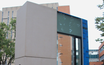
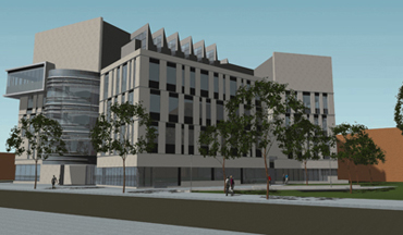
The USB embodies a completely different aesthetic than the surrounding campus buildings, both in style and material usage (see Figure 1). However, the differences reflect the university’s commitment to sustainable, functional buildings in a tangible departure from the old architectural style. The classrooms are located on the first floor for easier access to the general student body, whereas the laboratories and offices are on the upper floors. The distinctive five-story atrium serves as a gathering place for the building occupants as well as the university community at large, as the building is located next to a major pedestrian thoroughfare. The atrium also houses the four-story biowall and a distinctive spiral staircase (see Figure 2). In keeping with the exterior look, the interior finishes are largely stone, tile, glass, and aluminum, creating a streamlined, modern feel.
|
|
 |
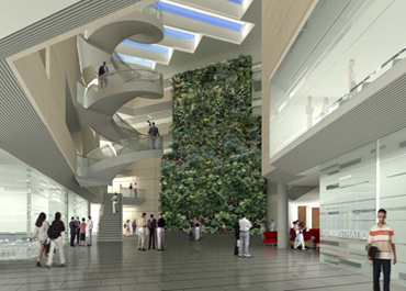 |
| Figure 1 Juxtaposition between USB wall mock-up (foreground) and typical campus architecture (background) | Figure 2 Interior render of the atrium showing the biowall and spiral staircase |
Major Codes |
|
The main building code used is the 2006 International Building Code (IBC 2006) with Local Amendments. By this code, this building is Construction Type “1B Protected Noncombustible Construction”. The building must also adhere to the 2006 International Mechanical Code (IMC 2006) with Local Amendments, the 2006 International Electrical Code (IEC 2006) with Local Amendments, the 2006 International Fuel Gas Code (IFGC 2006) with Local Amendments, and the Local Fire Code based on the 2006 International Fire Code (IFC 2006) with Local Amendments. |
Zoning |
|
The USB is located in a zone type utilized by the local municipality for university campuses. This district has an unlimited story height and no front, side or rear setback requirements. However, only 70% of the lot may be used as occupied space, and the Maximum Gross Floor Area is 400%. The building height is dictated by IBC 2006 requirements to avoid high-rise construction code provisions. |
Historical Requirements |
|
This building has no historical requirements. |
Building Enclosure |
|
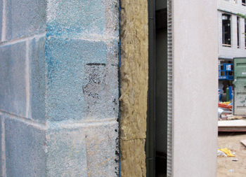
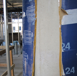
The facade is largely comprised of stone veneer and tall, thin windows of varying width. The stone veneer is an extremely thin layer of stone over honeycomb aluminum (see Figure 3) to reduce the weight of the facade, which is hung from CMU or cast-in-place concrete back-up walls. The thick walls were selected over lighter, less costly steel framing to minimize noise transmission from the exterior. The windows are unitized curtain wall panels with structural silicone glazing. They are placed on the building seemingly at random (see Figure 4), and provide natural lighting to most interior spaces. The penthouse, the only departure from the stone facade, is clad with a prefinished metal panel system. The roofing system on the building is entirely comprised of Thermoplastic-Polyolefin (TPO) single-ply membrane over rigid insulation, as none of the roof areas are accessible to the public. This is supported by concrete or 3” roof deck on W-shape framing, depending upon the location and function of the roof.
|
|
 |
 |
| Figure 3 Wall mock-up showing stone-aluminum honeycomb veneer panels and a CMU back-up wall | Figure 4 Exterior render showing the variety of sizes and placement of windows used |
Sustainability |
The USB was designed to achieve a LEED Silver rating upon completion of the building. One of the most notable sustainable features of the building is the four-story biowall, the first of its kind at a US university. Located in the building’s atrium, the biowall will serve as a natural air filtration system. Much of the return air in the building is routed into the atrium in order to take advantage of the biowall’s unique capabilities to control humidity and filter out carbon dioxide and volatile organic compounds (VOC’s), thereby improving indoor air quality. Other features include low water consumption toilets and urinals, natural lighting, and construction waste management. |
| Structure | |
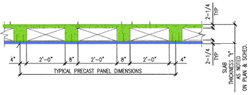
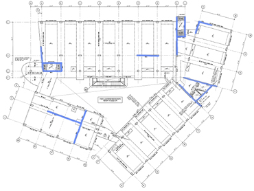
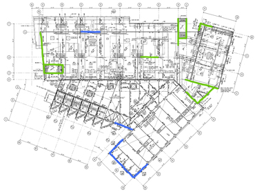
Geosystems Consultants, Inc. performed several test borings on the proposed site of the USB in October 2007. They found that the subsurface conditions consisted largely of extremely loose brick and rubble fill, followed by alluvium and finally residual soils with relatively low load-bearing capabilities. However, relatively intact bedrock was encountered approximately 25 feet to 34 feet below the surface of the site. Groundwater was found to be present on the site approximately 13 feet to 18 feet below the surface of the site. It was determined that this would only be a potential concern in the excavation of the basement. Lastly, it was recommended that the fill under the slab on grade (SOG) that comprises the majority of the first floor be removed to a level of approximately 4 feet below the surface, followed by heavy compaction of subsurface materials, and then backfilled with structural fill to minimize settlement of the SOG due to the extremely poor load-bearing capacity of the brick/rubble fill. In light of these conditions, traditional shallow spread footings would not be acceptable. Both driven steel H-piles and drilled caissons were considered as options for deep foundations, but H-piles were rejected due to vibration concerns within the subway station adjacent to the site, as well as noise concerns for the surrounding academic buildings. Instead, drilled caissons (3,000 psi concrete) ranging in diameter from 36” to 58” were chosen to carry the loads from grade beams to the bedrock below. Moving up the structure, the main superstructure is composed of large concrete columns, both round and rectangular, connected by a voided filigree slab system. This filigree system is a hybrid of precast and cast-in-place concrete slabs. It uses “leave-in formwork” of 2 ¼” of prestressed precast concrete, on top of which is poured an additional 8” of concrete. Where the full depth 10” slab is not required for strength, voids are incorporated through the use of polystyrene as a fill material (See Figure 5). A typical bay is approximately 21’-0” in the slab span direction, and up to 36’-6” in the girder span direction (See Figure 6). The lateral forces in the structure are resisted on these levels by 14 shear walls scattered throughout the building plan (See Figure7). The exterior walls above grade are CMU infill walls between the columns, chosen to limit the amount of noise transmission from the urban environment around the building rather than for structural strength. |
|
 |
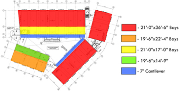 |
Figure 5 Typical section through a voided filigree slab, modified from Detail 1/S016. The precast concrete is shown in blue, whereas the cast-in-place concrete is in green. |
Figure 6 Typical floor plan, taken from Sheet S203. Approximate bay sizes are indicated with different colors. The legend is listed as "Slab Span"x"Girder Span". Areas without designation are irregularly shaped bays. |
 |
|
| Figure 7 Floor plan taken from Sheet S203 with the shear walls highlighted in blue. | |
The mechanical penthouse, which adds another story to most of the structure, is structural steel rather than concrete. It seems likely that this choice was made because the penthouse doesn’t need the sound-dampening effects of the heavier structure used below. It is mostly W-shape columns topped by W-shaped framing on the same grid as the concrete columns below, although the framing by the skylights is comprised of HSS members. The lateral forces at this level are resisted by five braced frames as well as the shear walls which continue up to this level (See Figure 8). The lower roofs (See Figure 9, red and orange roofs) are continuations of the filigree slabs of the floor they are adjacent to, whereas the upper roofs are 3” roof deck on top of steel framing. |
|
 |
|
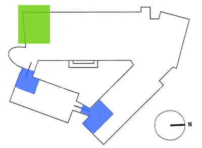
Figure 8 Roof plan taken from Sheet S206 with the braced frames highlighted in blue and the shear walls still in effect highlighted in green. |
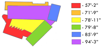
Figure 9 Simplified roof plan image from Sheets S205 & S206 showing different roof heights with relation to ground level (0’-0”). |
| Construction | |
The first issues encountered by the construction team were connected to the foundations. It was discovered that one corner of the site used to be a gas station, which had caused significant soil contamination. This condition had to be remediated prior to construction in this area. Also, drilled-in soldier piles and lagging had to be utilized for the basement excavations because the proximity and depth of footings of the nearest building didn’t allow the minimum allowable slope for unshored excavation. Above grade, the main difficulty facing the construction team of the USB was the sequencing of this structure. Per instructions from the structural engineer, the “link” portions of the building must be placed last on each floor (See Figure 10), after the rest of the floor has been allowed to cure for at least one day. This prompted the choice to begin construction in the southwest corner of the site, and to progress clockwise around the floorplan. Additional challenges mostly arise from the architectural design of the building. The irregular sizes and placement of the windows on the building facade require very careful quality control to ensure they are placed properly. On the interior, many of the large concrete columns are to be architecturally exposed concrete. To achieve the smooth finish desired, “Sonotube” formwork was used wherever possible instead of the more traditional fiberglass formwork (See Figure 11). Lastly, in order to effectively place the finishes on the interior of the building, the atrium will be entirely filled with scaffolding once the atrium SOG is poured. The erection of this scaffolding is a major undertaking that will vastly simplify the completion of the interior of the building. |
|
 |
|
| Figure 10 A simplified floor plan diagram taken from Sheet S202. The links, which must be poured last, are shown in blue. The Southwest corner is indicated in green. |
Figure 11 A Sonotube form pulled open slightly to expose the smooth architectural concrete finish below. |
| Mechanical |
There are three main mechanical rooms in the USB, one located in the basement, one on the fifth floor, and one which comprises the majority of the penthouse level. The basement mechanical room holds a 360 US gallon fuel oil tank, the fuel oil pump, the pumps associated with the biowall, and the domestic hot water system. The fifth floor mechanical room holds four air handling units (AHU 1, 4, 6 and 9) as well as secondary chilled water pumps, heating pumps, and glycol heating pumps. The largest mechanical room, located in the penthouse, contains the remaining five AHU’s, two 620 ton capacity chillers, the primary chilled water pumps, and the condenser pumps which serve the AHU’s. The nine AHU’s on the project range in size from 6,000 to 42,500 CFM, and are located in an attempt to minimize the lengths of the duct runs to the spaces they serve. The four AHU’s serving the laboratories (where 100% outside air must be used in the space to prevent any contaminants generated in the labs from reentering the building) utilize glycol heat recovery units (GRHU’s) to minimize the energy lost when return air is expelled. The spaces themselves are served by variable air volume (VAV) boxes with duct-mounted reheat coils to provide space-specific heating and cooling and to help maintain negative pressure in certain rooms (such as the labs) as appropriate. |
| Electrical |
The main power is fed from the nearest existing classroom building, which has a spare 13.2 kV breaker. It is brought to the USB via one Kerite 3-conductor 15 kV #4/0 cable (See Figure 12) in 4” conduit through an underground ductbank to the new 13.2 kV switchgear located in the electrical room in the basement of the USB. One line equipped with a 600A disconnect switch and a 30A fuse runs on one Kerite 3-conductor 15 kV #2 cable directly from the switchgear to the fire pumps. There, it is transformed via a 112.5 kVA transformer to 480V to appropriately serve the fire pumps. The main feed line within the building is one Kerite 3-conductor 15 kV #4/0 cable which has a 600A disconnect switch and a 150A fuse. This runs from the main switchgear to the largest electrical room, located on the fifth floor. There, it is transformed to 277/480V power by a 3325kVA transformer before feeding the 5000A main switchboard. This switchboard feeds the chillers, motor control centers, the emergency power (which is used for the emergency lighting system), the standby system (which is used for certain receptacles and motors), the emergency generator, and a 1000A, 277/480V 3-phase, 4-wire bus duct riser. The lighting panels in the building are fed directly at 277/480V from the bus duct riser. However, the receptacles require 120/208V power. This is provided by 4 additional transformers located in the electrical closets on the basement level (serving the basement and ground floors), the 3rd floor (serving the 2nd and 3rd floors), the 4th floor (serving the 4th floor), and the 5th floor (serving the 5th floor). These transformers connect the bus duct riser to the receptacle power panels. The 600 kW diesel generator is located on the roof of the building, and is supplied with fuel from the fuel oil tank and the corresponding 1/3 hp pump. It powers the emergency system, the standby system, and the fire pumps in the event of a power failure. |
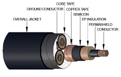 |
Figure 12 Kerite 3-conductor cable used as the main feed wires for the building. Image is from Kerite's Catalog. |
| Lighting |
There are 56 different types of lighting fixtures used in the USB.
The LED fixtures are used mostly as accent lighting in the atrium, such as around the perimeter at the roof level and on the handrails of the spiral staircase, or outside to light entrances or walkways. The fluorescent fixtures are the main bulk of the lighting in the building, and vary in style according to their application. These include direct/indirect suspended fixtures in the offices, downlights in classrooms, ceiling-mounted troffers in hallways, labs and large classrooms, and wall washers used to light whiteboards in classrooms. Energy efficient lamps and ballasts are required for all fixtures. Natural light has also been incorporated into the building as much as possible. It is provided to the atrium via skylights, which are positioned to allow light to fall onto the biowall (see Figure 2). Windows are incorporated into most of the laboratory and office spaces, with some taking advantage of the atrium to receive their natural lighting. |
| Fire Protection |
The building is mostly protected by a wet pipe fire suppression system. Pendant heads are the most commonly-used sprinkler type, although some concealed and upright heads have been also been incorporated. The main fire pump supplying the system is rated at 100hp and 1000 gallons per minute (GPM), and is equipped with a jockey pump rated at 2hp and 10GPM. Two rooms are not supplied by the typical wet pipe system. The Chemical Storage room on the ground floor is equipped with a carbon dioxide fire suppression system in the event of chemical fires. The loading dock, which may be exposed to temperatures which would cause a wet pipe system to freeze, is equipped with a glycol assembly. |
| Conveying Systems |
| The USB is equipped with one passenger elevator rated at 3,500 lbs which will serve the general public and have access to the basement up to the fifth floor. This is directly adjacent to the service elevator, rated at 5,000 lbs and has access to the basement to the penthouse. The building also has three major staircases, which include the spiral staircase in the atrium and two fully enclosed egress stairwells. There is also a single-story staircase at the back of the Auditorium to provide egress for anyone who may be in the mechanical spaces in the basement in the event of a fire. |
All Renders Graciously Provided by Turner Construction Co.
Senior Thesis Home Page | Pennsylvania State University | Architectural Engineering | Contact Me
User Note: While great efforts have been taken to provide accurate and complete information on the pages of CPEP, please be aware that the information contained herewith is considered a work‐in progress for this thesis project. Modifications and changes related to the original building designs and construction methodologies for this senior thesis project are solely the interpretation of Kathryn Gromowski. Changes and discrepancies in no way imply that the original design contained errors or was flawed. Differing assumptions, code references, requirements, and methodologies have been incorporated into this thesis project; therefore, investigation results may vary from the original design.
Last Updated: 10/11/10 by Kathryn Gromowski
This webpage is hosted by the AE Department © 2010/2011