Building Name:
Butler Memorial Hospital: The New Inpatient Tower
Location and Site:
One Hospital Way, Butler, PA
Building Occupant Name:
Butler Health Care Providers
Occupancy/Function Types:
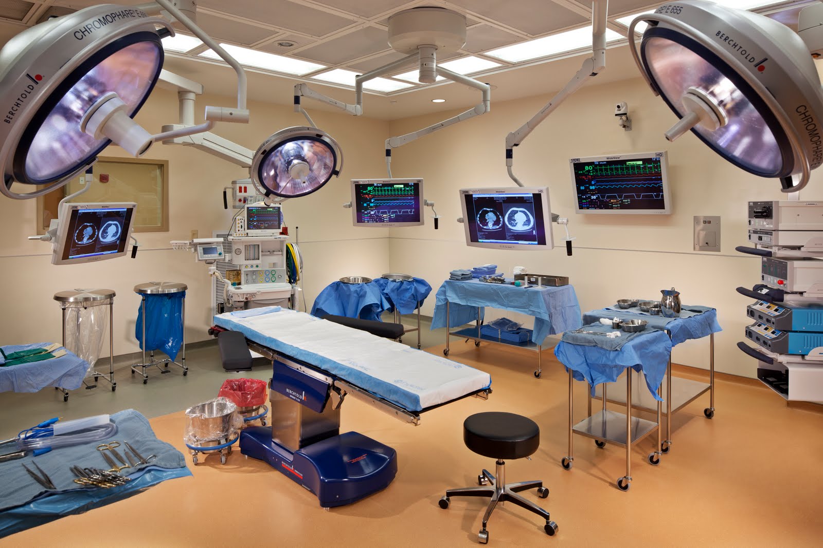
Hospital: Surgery, Recovery, and Critical Care Units
|
 |
Size:
209,678 sqft
Stories:
Above Grade – 6 (Including Penthouse); Below Grade – 2
Owner:
Butler Healthcare Providers (http://www.butlerhealthsystem.org/Pages/Home.aspx)
General Contractor/Construction Manager:
Turner Construction Company (www.turnerconstruction.com)
Owners Representative:
Ritter Construction Management (www.ritterpm.com)
Architect:
Design Group (www.dgcolumbus.com)
Design Architect/Engineer:
Hammel, Green, and Abrahamson, Inc. (www.hga.com)
Civil Engineer:
Pedersen & Pedersen (www.pedersenx2.com)
Technology Engineer:
KJWW Consulting Engineers (www.kjww.com)
Equipment Planner:
Korbel Associates (www.korbel.net)
Elevator Consultant:
VDA (www.vdassoc.com)
Dates of Construction:
September 2008 – July 2010
Costs:
93 Million (GMP)
Project Delivery Method:
Design Bid Build |
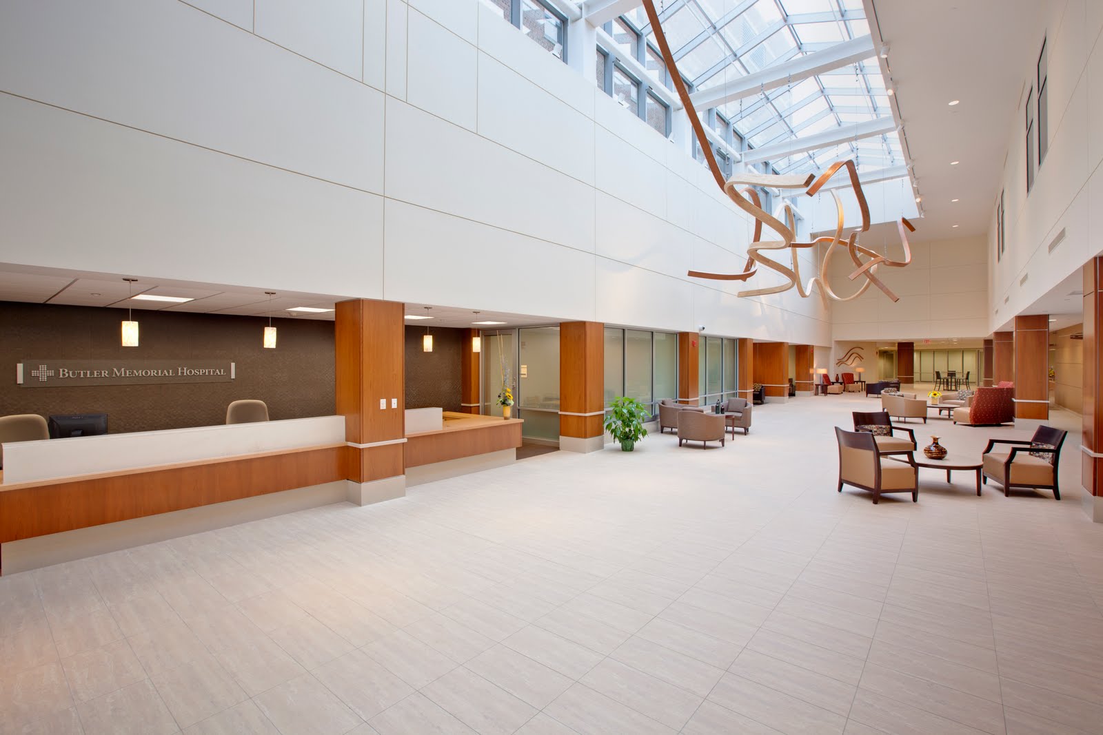 |
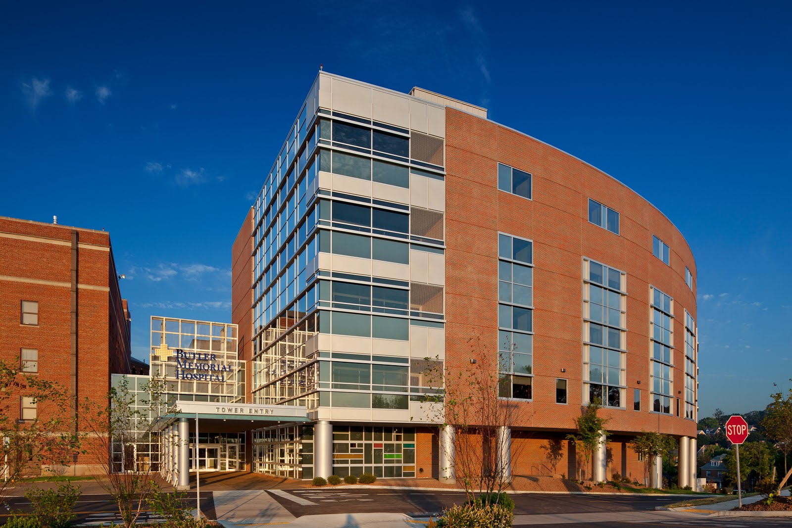
Architecture:
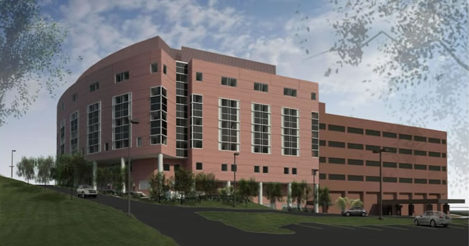
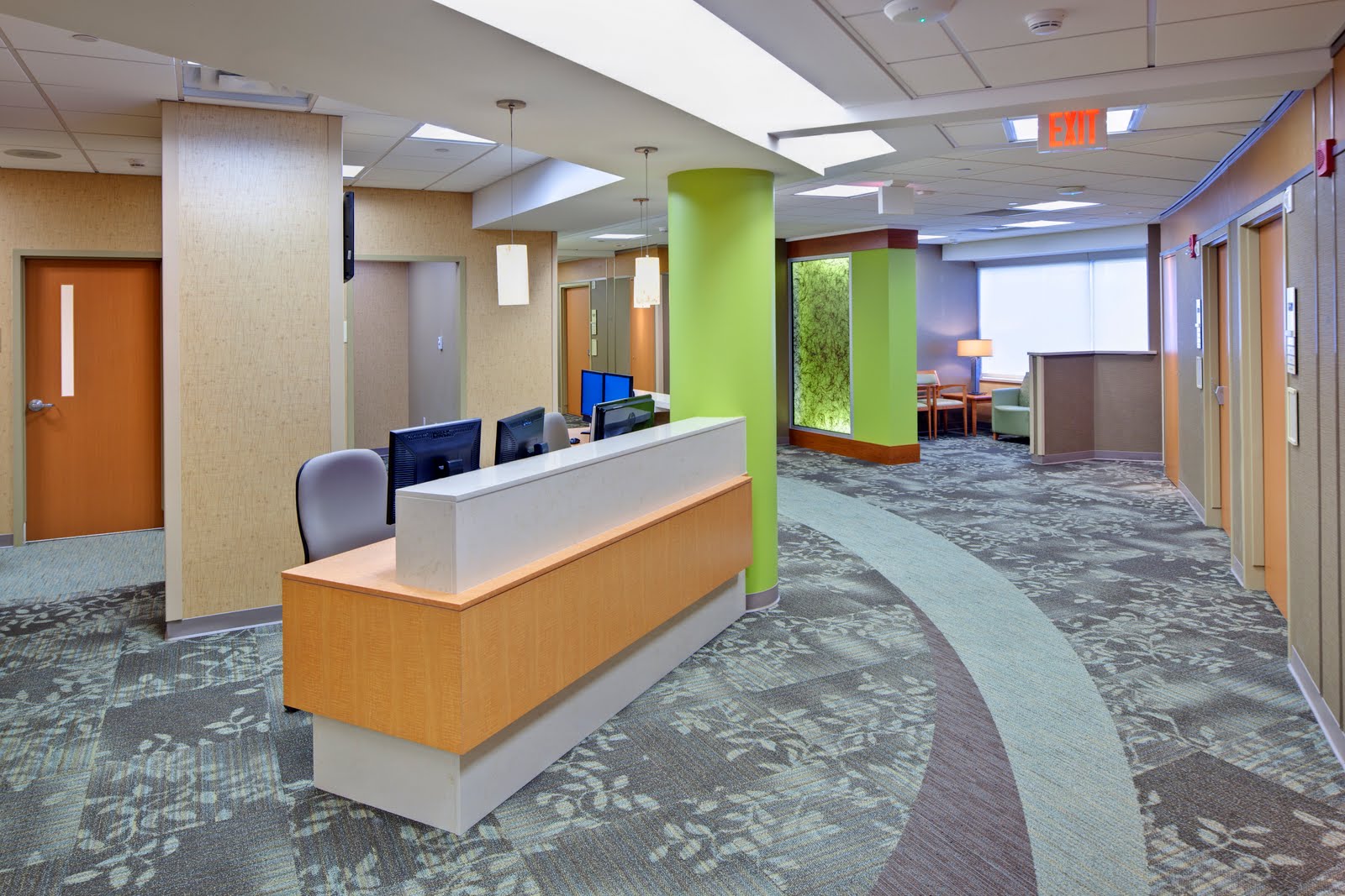
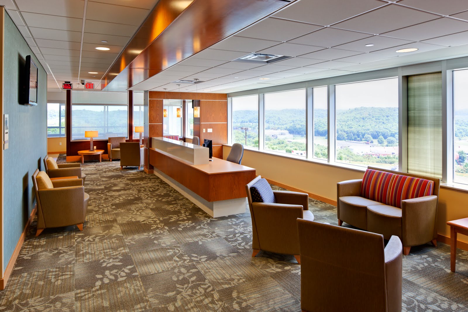
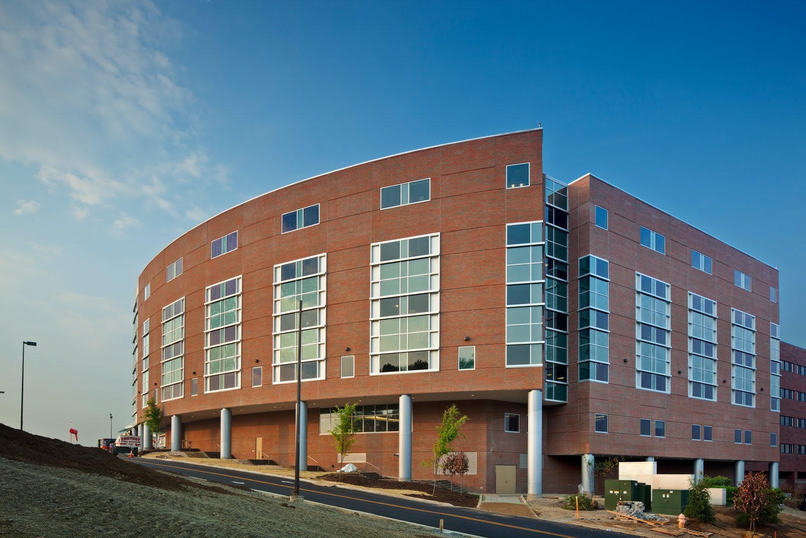
The overall architecture of the New Inpatient Tower of the Butler Memorial Hospital is integrated very nicely into the existing portions of the hospital,l as well as surrounding buildings scattered about downtown Butler. Red brick veneer, and tinted curtainwalls with aluminum trim comprise the majority of the exterior; which also happens to blend nicely with the existing red brick of the original hospital. The North elevation is curved and also steps down with contour of the existing hillside as it wraps around towards the west side of the building. After making the turn west, the ground continues to slope which is highlighted by aluminum cladded columns which dot the North and West perimeter of the building. Upon entering the inpatient tower through the main entry of the north façade on the second floor, a grand atrium 2 stories high is capped off by a full length triangular skylight in order to greet visitors with open arms. The remainder of the second floor is filled with public retail, convenience, and waiting areas, an auditorium, a chapel, several offices and conference rooms, as well as employee locker rooms. The third floor is mainly dedicated to surgery, equipped with operating rooms, an anesthesia administration area, and immediate recovery rooms. In order to match the existing hospital, the floor above the third floor is not the fourth, but instead the fifth floor which is primarily composed of critical care units. The upper floors, six and seven, are identical and devoted to long term surgery recovery rooms. Above the seventh floor is the penthouse, which houses the elevator machine room and is adjacent to the rooftop air handlers. A second entrance at a lower elevation on the west façade allows maintenance personnel to enter directly on the ground floor with immediate access to the emergency generators and storage areas. Between the ground floor and second floor, the first floor is home to the mechanical and electrical rooms. The overall architecture of the hospital has a contemporary vibe equipped with flat screen televisions in every patient’s room, vibrant and lively color schemes, and architectural sculptures which help to create a positive feeling within the tower.
Codes:
2006 International Building Code
2006 Guidelines for Design and Construction of Health Care Facilities
1998 Pennsylvania Department of Health Rules and Regulations for Hospitals
2000 National Fire Protection Agency 101
Zoning:
City of Butler Zoning Regulations
1-2 Hospital (Non-separated mixed use)
1B - NFPA Type 2 (222)
Building Enclosure:
Façade: The majority of the exterior façade is deep red face brick veneer with a 1” air cavity, followed by 2” rigid insulation, and 5/8” gypsum wall board attached to 6” steel studs which are filled with batt insulation between studs. The exterior glazing is primarily 1” tinted insulating glass comprised of ¼” tinted exterior light equal to PPG Gray with low “E” coating matching Viracon VE3-2M with a ½” air space and then ¼” clear interior light; and 1” insulating spandrel glass comprised of ¼” clear exterior light, ½” air space, and ¼” spandrel interior light with ceramic frit equal to Viracon Subdued Gray. These two window types are used exclusively with 1/8” Aluminum panels to create a glazed aluminum curtainwall system. Wire cloth screening, clear glass, laminate glass, and fretted glass are also used sparingly in order to make the façade more interesting.
Roofing: The roof of the new tower is comprised mainly of a mechanically fastened membrane system. The system uses a white 60 mil thermoplastic polyolefin (TPO) membrane formed into flexible, uniform sheets and then mechanically fastened together. Fully adhered EPDM single ply membrane is to be used to top of canopy roofs.
Sustainability Features:
The use of radiant heat ceiling panels line the perimeter of building, giving patients more thermal comfort control and reducing heating costs. Low “E” tinted glass will help reduce solar gain and therefore reduce the cooling load and energy consumption. Motion activated sensors controlling illumination will allow for lights to be engaged only when occupants are in the room, thereby conserving electricity. Natural daylighting is used extensively throughout patient’s rooms as well as in the atrium area, where magnificent skylights illuminate the main entry way and public areas on the second floor.
Mechanical
The system is a variable air volume system with terminal boxes located near diffusers for flow control. 100% outside air economizer cooling is installed on all air handlers to save on cooling costs during temperate weather. The system configuration has redundancy in the chiller water system, with the ability to lose the chiller, pump, or cooling tower and remain functional. Radiant heat is used extensively in patient rooms along the perimeter of the building to provide individual thermal comfort control. There are a total of 8 air handling units with the 5 main units being VAV and the remaining 3 smaller units being constant volume.
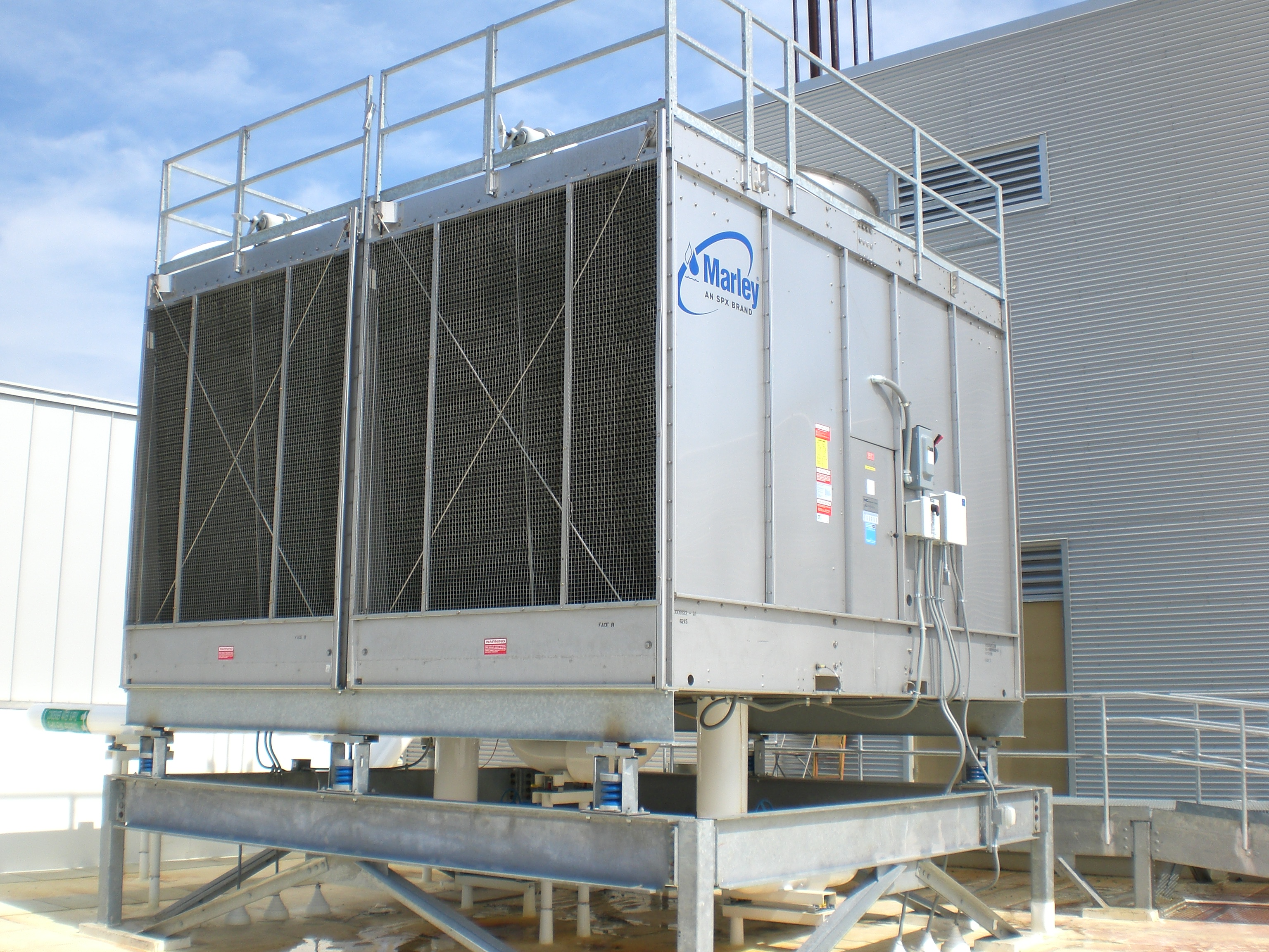
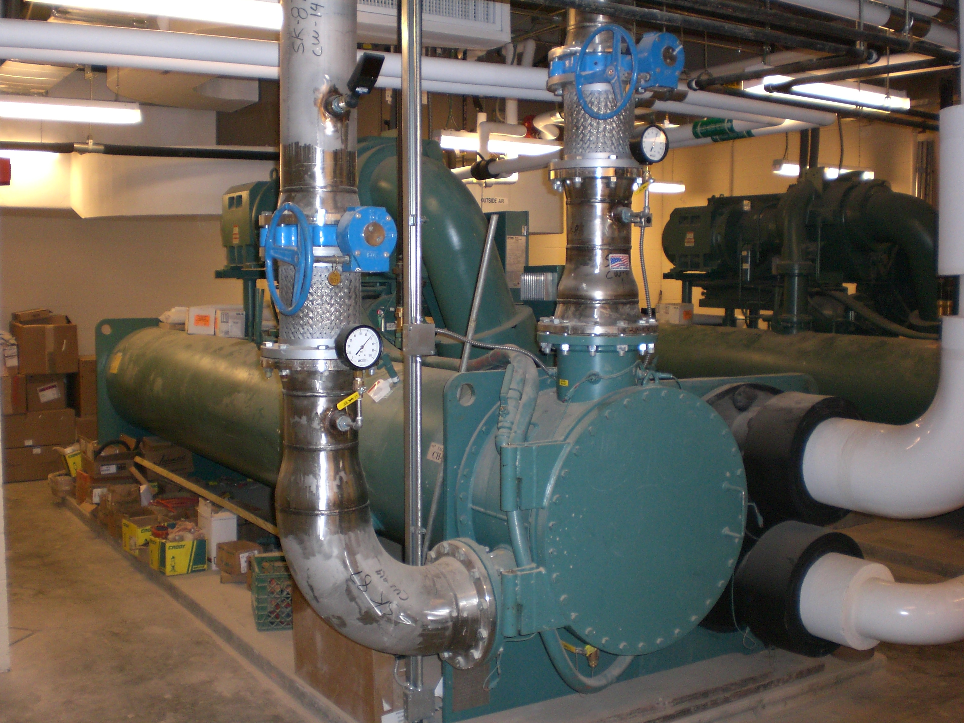
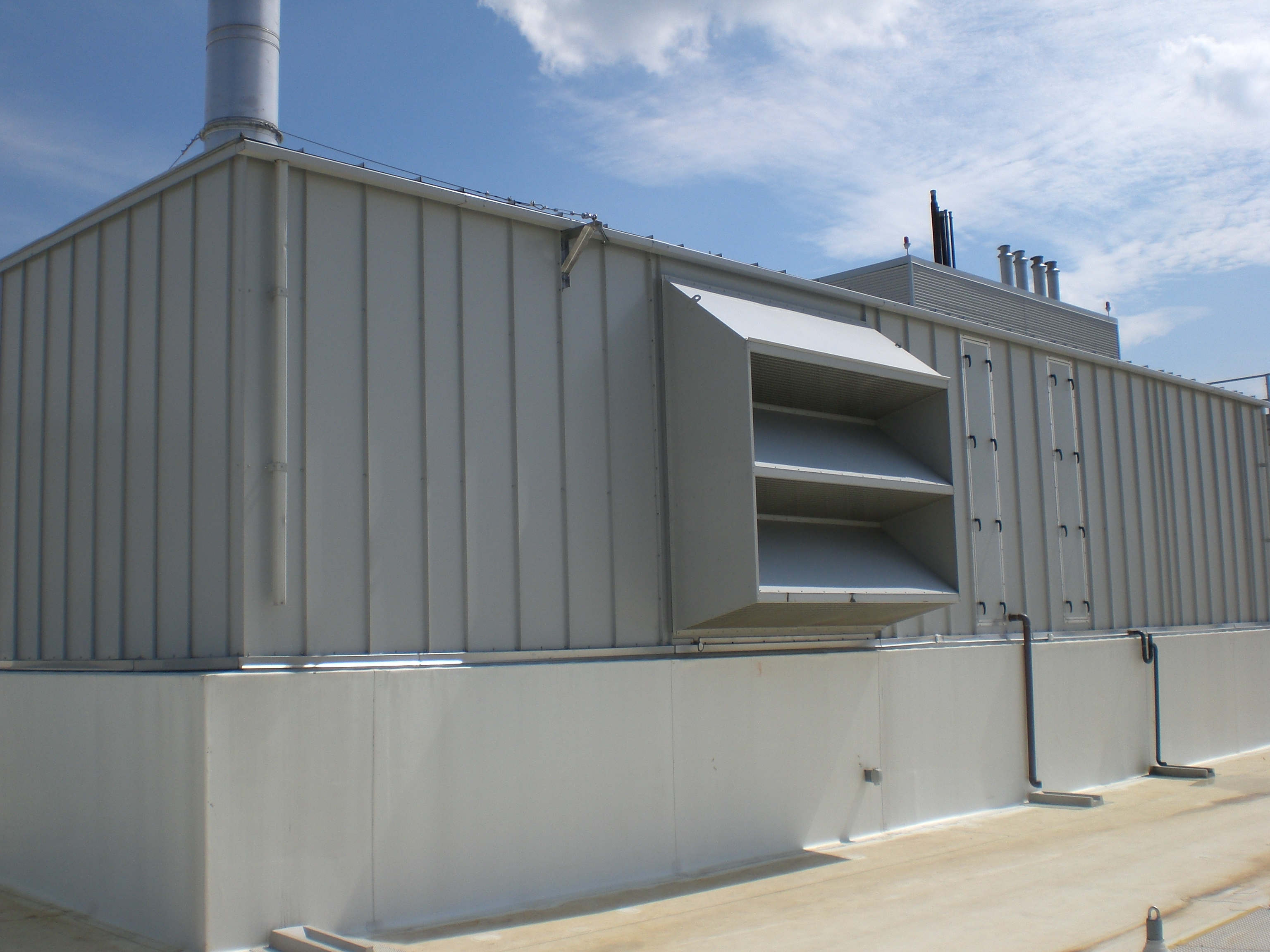
The primary heating, air conditioning, and ventilation is performed by (3) 62,000 CFM rooftop air handlers. These three air handlers comprise a loop system which serves every area of the hospital except for operating rooms and a few mechanical rooms. Due to the nature of the loop system, all 3 air handlers are coupled feeding every diffuser, there is natural redundancy built into the mechanical system. (2) 400 ton centrifugal chillers with variable speed drives provide AHU 1, 2, & 3 with cold water used for dehumidification and cooling. A central rooftop cooling tower serves as the primary means of cooling the condenser water which exits the two centrifugal chillers.
Rooftop air handling units 4 and 5 are located on a lower level roof and provide the necessary heating, ventilating, and air-conditioning to the 8 operating rooms which are located on the 3rd floor. The operating room air handlers are serviced by an adjacent 119 ton air-cooled scroll chiller supplying 34°F water. The lower temperature system is backed up by the primary chillers in case of emergency; 45°F primary water can still be supplied.
Air Handling Units 6, 7, & 8 are all smaller units which serve specific rooms with an extra need for cooling. AHU-6 and AHU-7 service the chiller and electrical room respectively. Both of these components utilize the 2 main chillers and boilers as there thermal source. AHU-8 serves the elevator machine room.
On the heating side, (2) 215 BHP combustion gas/oil-fired hot water boilers supply all of the heating water for the entire building: this includes heating water to the air handling unit heating coils, unit heaters used for reheat within terminal boxes, duct heating coils, radiant ceiling panels around the perimeter of patient rooms, and finned tube radiation in the soffit/plenum area above the second floor to keep the cantilevered floor warm.
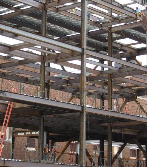
Structural
The hospital is supported by steel wide flange beams and columns which are carried by poured concrete caissons, ranging in diameter from 30” – 80”, and grade beams. The majority of the columns are W 14 with weights ranging from 43 – 176 lbs/ft. Although various wide flange beam sizes are used, the majority of the hospital is supported by either W16x26 or W18x40. Resting on top of the wide flange beams is a composite metal deck system with 5” shear studs and 3-1/2” of concrete topping for a total floor height of 6-1/2”. Columns are laterally braced using K frame braces in both directions. 10” K frames are used on levels 1 – 3, and 8” K frames are used on the upper levels. Typical exterior wall construction is face brick with 2” rigid insulation mounted on 6” steel studs with gypsum wall board on both sides.
 |
 |
Electrical
The hospital is serviced with 3 phase, 4 wire incoming service at 480/277V. The main feed is from the existing hospital and enters the addition vie the first floor mechanical room. Within the mechanical room a 2,500 kVA transformer reduces the voltage to that which is suitable for building distribution. There are electrical rooms on every level capable of supplying 480/277V and 208/120V. The high voltage is used primarily for running heavy equipment, motors, and fans as well as fluorescent lights. The lower voltage is for general use throughout the hospital including incandescent lights, receptacles, and office equipment. There are also (2) emergency generators located on the ground floor directly under the main electrical room. These will provide back-up power in case of power outage.
Lighting
Within a hospital there is obviously a need for various kinds of light fixtures. The Butler Memorial Hospital New Inpatient Tower is no exception. There are over 85 different types of light bulbs which are all serving a specific function. The lighting is all served by either 277V, which is used for all fluorescents, or 120V which is used for incandescent. These lights serve various functions from wall washing, to accent lighting in the chapel, to providing the highest quality of light for operating rooms.
Fire Protection
The hospital is equipped with state of the art fire protection. When designing the building, engineers took special care to install smoke partitions and dividers so that smoke cannot travel freely throughout the building. A spray on fire-proofing has been applied to all steel structural members to ensure the integrity of the steel under fire conditions. Lastly, there is an integrated sprinkler system which supplies every room within the hospital with a Siamese connection at ground level for fire department hook-up.
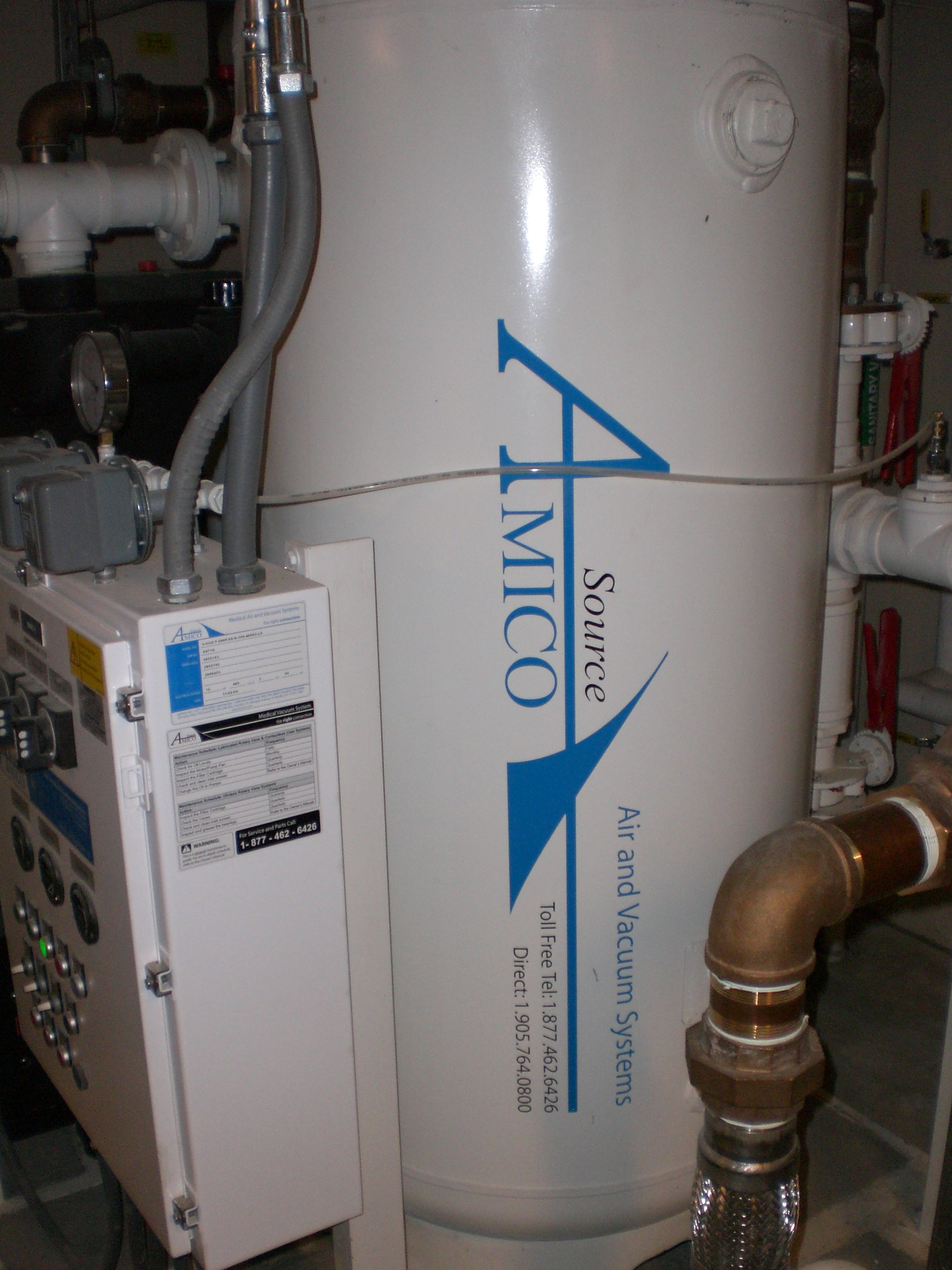
Pneumatic Tube Delivery
The hospital is equipped with a compressed air driven tube delivery system which allows nurses to transport tangible objects in a more expedient manner. Hospital personnel are able to send documents, files, and even medications through the system. The system was designed and developed by Swisslog, which uses a compressor manufactured by Amico. By using the pneumatic system, it allows for less corridor traffic and busy work for staff, thereby increasing efficiency and the standard of care for patients.
|