General Guilding Information |
Building Name |
- |
The University Sciences Building |
Location |
- |
Northeast, USA |
Occupant |
- |
Withheld by the Owner |
Function |
- |
Laboratory/Classroom/Office |
Size |
- |
209,000 s.f. |
Height |
- |
117' |
Number of Stories |
- |
2 below grade/7 above grade |
Construction Dates |
- |
August 2006 - December 2009 |
Construction Cost |
- |
Withheld by the Owner |
Delievery Method |
- |
Construction Manager at Risk |
|
|
Owner |
- |
Not Released |
Architect |
- |
Mack Scogin Merrill Elam Architects |
Associate Architect |
- |
Edge Studio |
General Constractor |
- |
P.J. Dick Inc. |
WBE Contractor |
- |
Graziano Construction and Development |
Structural Engineer |
- |
ARUP |
Mechanical Engineer |
- |
ARUP |
Electrical Engineer |
- |
ARUP |
Civil Engineer |
- |
Civil and Enviornmental Consultants |
For a .pdf of Building Statisitcs 1, click here. |
Architecture |
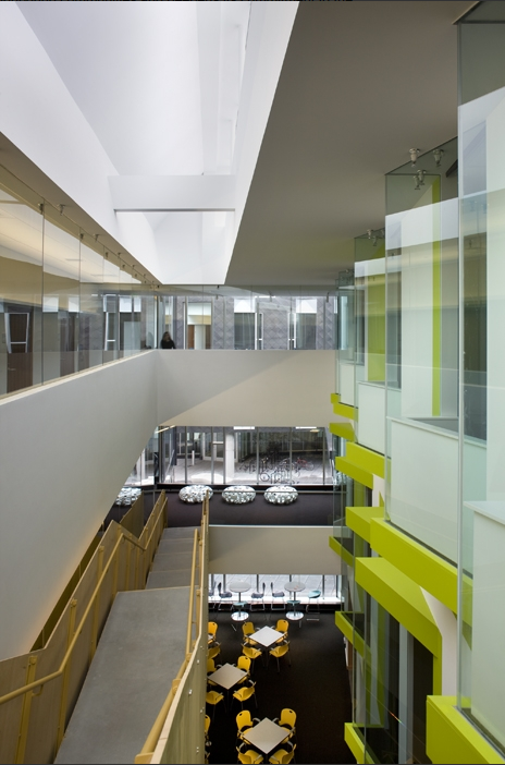
Located in the center of the urban campus, The University Sciences Building sits with a modern and distinct look with its unique materials and innovative architectural features. Its LEED Gold Certification makes it the campus' most sustainable building. The USB conssits of two buildings connected by a 6 story passage.
Building 1 has 7 stories above grade and 2 below. The core of Building 1 is its featured 3 story Helix ramp. This helix is a concrete formed ramp to 3 different floors with classrooms at the center. The bottom 5 floors of building 1 ar4e primarily used for classrooms and ,laboratories. The top 3 floors are used for offices and conference rooms. Building 1 has 2 unique atriums. One is incorporated with the helx structure and the others is a 3 story, 1420 s.f., atrium on 6th, 7th, and 8th.
Building 2 has 4 stories above grade and 1 below. The use of this building is primarily for research, including offices and laboratories. This building also utilizes the use of 2 atriums. The first is on the east side of the building; this 810 s.f. atrium spans floors 5-7. The second is on the west side of the building; this 370 s.f. atrium also spans floors 5-7 |
|
Building Enclosure |
The building gets its unique look from its facade. It incorporates black zinc lining panels with silver zinc siding bordering the plethora of windows in different shapes. Nearly every space in the building has exposure to natural light. Generated by elaborate windows and curtain walls, and exterior open to above atriums. |
Structure |
The University Sciences Building sits upon a Site Class C (ASCE 7-05 Chapter 11) on 30’’ drilled caissons, with caisson caps, spread, continuous, stepped, grade beams and column footings. Levels 1-3 of Building 1 and level 4 of Building 2 use concrete beams and slabs with a combination of concrete columns and steel encased columns. The upper floors of both buildings use a composite beam/slab system and continue with steel and encased columns. The lateral systems consists shear walls and braced steel frames. The shear/retaining walls start from the grade and end at various heights around the building. The braced frames are composed of wide flange chords with HSS diagonals that also reach various heights. |
Zoning and Code |
This building was designed and built under the International Building Code 2006 (IBC 2006), along with it's supplemnetal echanical and electrical codes. Structural Design followed the ASI 318 for reinforced concrete and ASIC LRFD 3rd edition for steel. |
Construction |
Construction of the USB started in August of 2006 and was completed in December of 2009. PJ Dick, Inc. was the Construction Manager at Risk to construct the USB at a price withheld at the owner's request.
The project experience many delays in construction. Other delays had occurred during design development stages which prolonged the start of construction. Inconsistencies with the geotechnical report delayed the final design of the foundations. A big delay in construction was the erection of the steel. The manufacture of the steel could not stay on schedule which delayed the shipment of material to site. Secondly, the erectors had a large task at hand of erecting the structure. Due to the geometric complexity to the framing for the system, the erectors were drastically behind schedule; delaying all other trades that follow.
The USB is essentially two buildings connected by a 4 story passage. The coordination to ensure each building starts and finishes at the same time was a challenging task for the construction team but completed on schedule. |
Mechanical |
The USB's main mechanical room is located on the third floor of both buildings 1 and 2. Located here is the buildings 8 pumps; 6 for hot and cold water system and 2 for the snowmelt system. This mechanical room also holds air handling units, a variety of duct work and other equipment.
The USB utilizes 11 different Air Handling Units types. They are located on the second, third and roof levels. They vary in size from 3,800 CFM to 40,700 CFM. Of these AHUs, 5 of them use a heat recovery wheel. These are utilized in areas that require 100% of outside air to be supplied so the condition room is not contaminated but can benefit from the already heated exhaust air.
The spaces in the USB use variable air volume (VAV) boxes. The VAVs air flow capacities are designed with different volume ranges, up to 2,600 CFM. This allows certain spaces to be conditioned differently per the use of that space. |
Electrical |
The USB is supplied by the Campus' 4.16 kV distribution system. It then enters the building in a 5kV primary selector load break switch rated at 100kAIC. This then transformed to 4.16 kV– 480/277V power 2500KVA transformer. This then feeds the main switchboard, a 4000 A copper bus, 480/277V, 3 phase, 4 wire, and ground with a 65 kA AIC short circuit, which is located on level 3. This main switchboard supplies both Building 1 and Building 2. Building 2 is feed by a 480V 225 A and a 208V 1200A busway risers and Building 1 is feed by a 480V 225 A and a 208 V 80A busway risers. These risers supply power to and branch off to different areas within each building.
Also feeding off the 2500 kVA transformer is a 100 HP fire pump. Extending from the fire pump controller is a 1 – HR fire rated emergency feeder that goes to the 1125 kVA/900kW fuel oil generator tank. Finally it ends its feed at the main emergency electrical switchboard before reaching the 135 kW standby power reserved for an adjacent building. |
Fire Protection |
The USB is fire protection with the assistance of a wet pipe fire suppression system. The system starts with a 800 A service rated fire pump controller that feeds a 100 HP fire pump with the assistance of a 3 HP jockey pump. The majority of spaces are serviced by concealed heads.
The USB also uses a smoke exhaust system in 3 atriums. All three spaces are connected to the same exhaust that has a total capacity of 200,000 CFM. These spaces are controlled by the fire and smoke dampers that activate the system.
In addition, three stairwells have pressurization systems to help maintain pressure in the event of a fire. |
Conveying Systems |
The USB has a total of 3 hydraulic elevators. Building one utilizes one 3500 lb passenger and one 5000 lb service elevator. Building two utilizes only one 3500 lb passenger elevator.
Also, Building one has two egress stairwells through the total height of the building and building two has one. The atriums in the USB have decorative stairwells. |
|