![]()
Structural Option
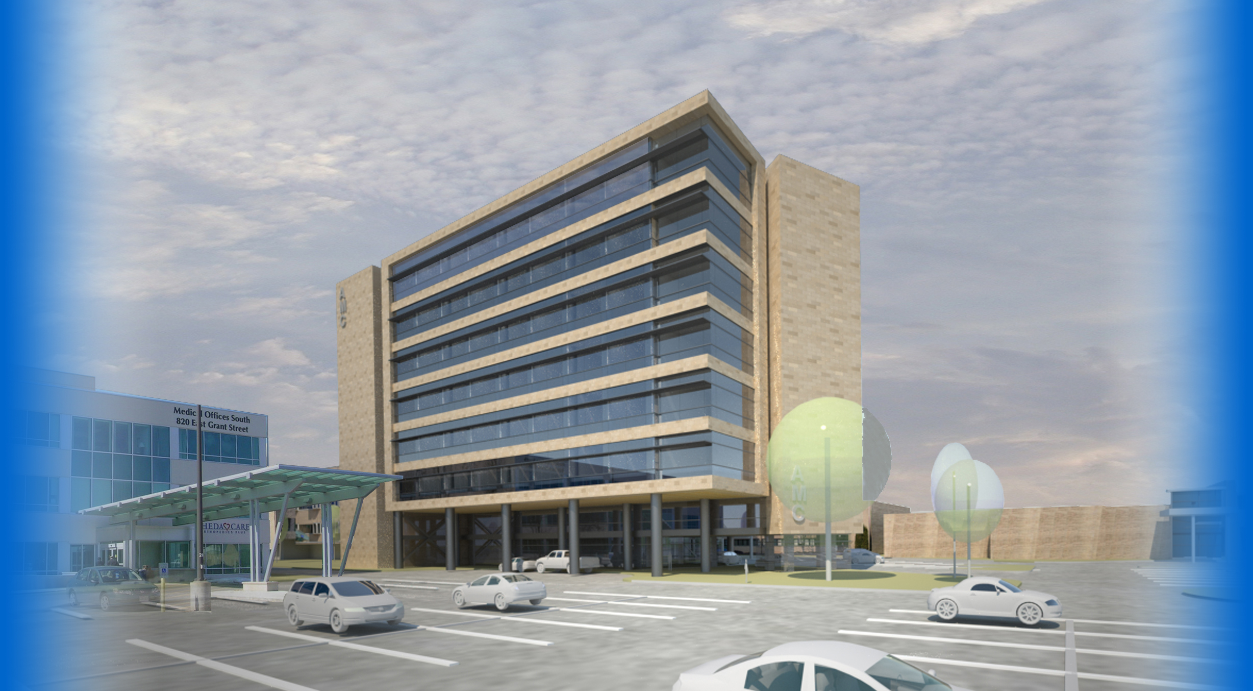
Bedtower Addition
@ Appleton Medical Center
Appleton, WI
Building Statistics: Part 1
Bed Tower Addition at Appleton Medical Center
General Information
Click Picture for Full PDF Version
of Building Statistics: Part 1
Building Name: Bed Tower Edition at Appleton Medical Center
Location: Appleton, Wisconsin
Building Occupant Name: Appleton Medical Center
Occupancy: Institutional Group ‘I-2’ (Hospital)
Size: 152,330 Sq. Ft.
Height: 107’-3” above grade to the high occupied floor
Number of Stories: 9 stories with basement
Start of Construction: Information was unavailable, waiting for response
Finished Construction: Information was unavailable, waiting for response
Cost: Information was unavailable, waiting for response
Project Delivery Method: Information was unavailable, waiting for response
Project Team
Owner: Appleton Medical Center
Construction Engineer: The Boldt Company
Civil: McMahon Associates
Architect: Hammel, Green and Abrahamson
Interiors: Hammel, Green and Abrahamson
Structure: Hammel, Green and Abrahamson
Mechanical: Tweet/Garot Mechanical
Electrical: Excellence Electric
Plumbing: Bassett Mechanical
Fire Protection: J. F. Ahern Co.
Architecture
The Bed Tower Addition has a unique triangular shape layout which is carried throughout all the floors of the building. The horizontal streaks of CMU along the exterior make the addition look very sleek and long. Accommodating the long streaks are large areas of glass. Both materials work together in order to show floor separation and this gives the perspective that the addition is deceptively taller than it looks.
The first floor is the lobby area which consists of the registration waiting area and registration along with a mini coffee shop. The second floor is the office area which is a very large space and movable partitions. The third floor to the eighth floor consists of the patient rooms, waiting rooms, and main floor manager offices. The second through fourth floor connects to the original hospital with the fourth floor extended into the original building which was renovated.
National Codes
The main building code used was the International Building Code (IBC) 2006 with state amendments. Mechanical followed the International Mechanical Code (IMC) 2006 with state amendments. Both of the latter codes were used as a guide for the Wisconsin Commercial Building Code (WCBC). Plumbing use d the Wisconsin Uniform Plumbing Code 2004. Electrical used the National Electrical Code 2005 with state amendments. The International Fire Code (IFC) 2006 as amended by the municipal code of the city of Appleton was used for the fire code.
Zoning
Zoning was determined using the Municipal Code of the City of Appleton, Wisconsin. It was published by the Order of the Common Council.
- C-2 General Commercial District
- Minimum lot area 14,000 square feet
- Minimum lot width is 60 ft
- Minimum front yard is 10 ft
- Minimum rear yard is 20 ft
- Max building height is 200 ft
Historical Requirements
No historical requirements were specified but I am double checking with the project manager just in case.
Building Enclosure
Building Facades
The building is enclosed by two essential components, one of which is the stone facade while the other is glazing.
The stone facade is made up of mostly cast stone making up the vertical facade and limestone making an appearance as a crown to the bottom of the building. The size of each limestone and cast stone masonry unit is 11-5/8 inches high by 23-5/8 inches long by 3-5/8 inches wide. The cast stone has a sandblast finish and the color is sandrift which looks like a tan-gold color. The limestone has a medium dressed finish and a blue-gray color.
There are three kinds of glazing making up the exterior of the building: 1) Clear Vision Glass 2) Tinted Visual Glass and 3) Spandrel Glass. The specifications indicate that the glazing was to be provided in order to be “capable of withstanding normal thermal movement and wind and impact loads (where applicable) without failure.”
The Clear Vision Glass is a low energy insulated glass which has a visible transmittance of 70 percent. This glass is used on the lobby exterior to allow a lot of natural light and heat gain during the day which can help the building warm up during the cold months of the year.
The Tinted Visual Glass and Spandrel Glass is combined together to make up the glazing for stairwells and patient rooms. The TVG is also a low energy insulated glass with a lower visible transmittance of 35 percent while the Spandrel Glass has a visible transmittance of 0 percent. Each have a nighttime winter U-Value of 0.29 BTU/hour/ft2.
Roofing
The roofing consists of a single ply roofing membrane on top of insulation which encompasses most of the roof. The slope and insulation thickness of the roof are both different at some parts of the roof. The drawings indicate where these areas are located.
Sustainability Features
After looking through drawings it does not appear there were any sustainable features but they might not have been included with the specs or drawings. I will be double checking with the project manager on this for further use.
Building Statistics: Part 2
Bed Tower Addition at Appleton Medical Center
Structural
Foundation – A mat slab foundation was used in order to resist overturning moment from lateral loads especially wind. Footings were designed for a soil bearing pressure of 4200 psf for gravity plus lateral loads. Typical reinforcement for the mat slab includes the use of #7, #9, and #11 bars running both ways. Total thickness for the mat slab is 3ft 6in.
Lateral System – Concentrically braced frames in each direction resist the lateral loads while the concrete slabs on metal deck act as the diaphragm which transfers the loads to the braced frames. There are 8 frames throughout the building accounting for both the north-south and east-west directions.
Floor Construction – Typical floor construction consists of 4 types of deck, two composite decks, a slab and roof deck. Most floors were constructed of 3in., 18 gage galvanized steel deck with a 4-½ in. normal weight concrete topping, making it a total thickness of 7-½ in. reinforced with 6x6 WWF. Bay sizes were typically set at 30 ft, especially on the outer spans of the building where the patient rooms are located. Beam sizes ranged from W14's to W30's throughout the building.
Fire Protection
The building is connected to an 8" water main pipe combined with a wet pipe sprinkler system. There is also an antifreeze system installed. The maximum rate of flow is 5290 gallons per minute at one part of the building. Fire department ready connections are located on the street sides of the building.
Mechanical
Heating – Hot water heating and chilled water cooling piping used. The building uses a low pressure steam system which the water would be transferred to steam to heat up serviceable areas. Steam is provided by a plant on top of the building. Some VAV boxes have a 2 row reheat coil to provide heat as well.
Cooling – Variable air volume (VAV) boxes are used to distribute cool air to various spaces of the building. Also installed, are radiant ceiling panels. They are temperature controlled surfaces which sensible heat is removed to cool indoor spaces.
Construction
The Boldt Company was the general contractor responsible for the construction of the bedtower addition. Construction started in June of 2008 and ended in January of 2011. Integrated project delivery was the delivery method used. Total area of addition ended up being 152,330 square feet. Cost of the building was an estimated $59,100,100.
Lighting
Waiting for additional information on lighting. Will be updated soon.
Electrical
Done by Excellence Electric, the main electrical output is powered by a 480/277 volt 3-Phase 60 Hz 1200 amp system. This powers most of the high powered electrical equipment to. There is secondary output powered by a 120/208 volt 3-Phase 60 Hz 100 amp system. This is used in smaller areas of the building where electricity is least commonly used.
Note: While great efforts have been taken to provide accurate and complete information on the pages of CPEP, please be aware that the information contained herewith is considered a work in progress for this thesis project. Modifications and changes related to the original building designs and construction methodologies for this senior thesis project are solely the interpretation of Jessel Elliott. Changes and discrepancies in no way imply that the original design contained errors or was flawed. Differing assumptions, code references, requirements, and methodologies have been incorporated into this thesis project; therefore, investigation results may vary from the original design.
This page was last updated on 01/17/2012, by Jessel Elliott
and is hosted by the AE Department 2011