 |
|
  |
|
|
MECHANICAL OPTION |
||
GENERAL BUILDING DATA
Project Name: INOVA Fairfax Hospital South Patient Tower
Location: Falls Church, Virginia
Occupant Name: INOVA Health System
Function: Hospital: Patient Bedrooms
Size: 236,000 SF
Number of Stories: 12 stories above grade + 1 below grade
Construction Dates: August 2010 to June 2012
Overall Project Cost: $76 million
Delivery Method: Design-Bid-Build
Contract: Single Prime with negotiated Lump-Sum contract
PROJECT TEAM
Owner: INOVA Health System
Architect: Wilmot/Sanz Inc.
General Contractor: Turner Construction Company
Structural Engineer: Cagley & Associates
Mechanical Engineer: RMF Engineering, Inc.
Electrical Engineer: RMF Engineering, Inc.
Civil Engineer: Dewberry & Davis
ARCHITECTURE
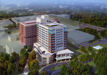
The INOVA Fairfax South Patient Tower was designed to complement and respect the recent Heart Institute to the building's west, while maintaining an architectural style that is consistent with the rest of the INOVA Fairfax Hospital Campus. It is designed to be a new addition to the existing patient tower. The building can be broken into two distinctive architectural parts; the lower three floors (podium) and the upper nine floors (tower). The podium section of the building hosts the entrance lobby, cafeteria, kitchen, services, offices and ultrasound exam rooms while the tower is strictly for patient bedrooms. A two floored atrium is used for the entrance lobby and has a circular fountain located on the ground level. The mechanical systems are located on the fifth floor due to a trauma helicopter pad located on the roof of the tower.
Major Codes
INOVA Fairfax South Patient Tower was designed per the following codes:
- Virginia Uniform Statewide Building Code
- International Building Code 2006, with local amendments
- International Mechanical Code 2006, with local amendments
- International Energy Conservation Code 2006
- International Basic Plumbing Code 2006
- National Electrical Code
The project also adhered to the latest rules, regulations, and recommendations from the following:
- Fairfax County Health Department
- Commonwealth of Virginia Health Department
Zoning
The INOVA South Patient Tower is located in Fairfax County, Virginia and falls under the I, Merrifield Suburban Center, Land Unit M, Sub-Unit M1 planning area and district. Innovative energy efficiency and conservation strategies should be incorporated into all new buildings in this district. A setback of 100 feet on the western boundary of the district and a maximum height of 165 feet are requirements within Sub-Unit M1.
Historical Requirements
This building has no historical requirements
BUILDING ENCLOSURE
Building Facade
The South Patient Tower consists of a curtain wall system for the exterior facade. This curtain wall is made up of three elements that help to respect the existing patient bed tower while mirroring the newer Heart Institute’s facade style. Precast concrete panels, aluminum curtain wall with glazing and metal panels all work together to create this building’s facade. There are two varieties of precast concrete panels. One is a panel formed into thin brick laid in soldier courses and help to tie the building into the older all brick patient tower, and the other is a basic precast panel in the center of each elevation and on the facade of the podium level. The aluminum curtain wall with glazing helps to provide ample amounts of daylight for the interior patient rooms and other interior spaces. Metal panels are used to continue to look of the building but help to hide some of the interior elements such as columns or the mechanical fifth floor.
Roofing
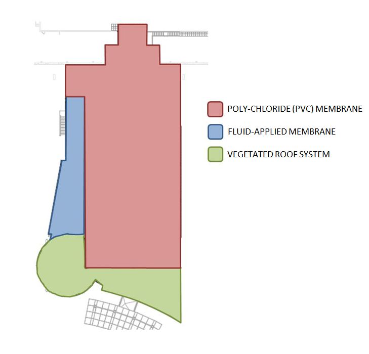
The roofing for the South Patient Tower consists of a similar base of a 9-1/2” reinforced concrete slab, insulation, and a 4” light-weight concrete topping for the three types of roofing materials on the project. Figure 2 shows the areas of each type of roofing material in plan view. These materials include; polyvinyl-chloride (PVC), a fluid-applied protected membrane, and a vegetated roof system. The lower podium roof consists of both the vegetated roof system and the fluid-applied protected membrane, while the higher tower roof is made of the polyvinyl-chloride (PVC) material.
SUSTAINABILITY
The INOVA Hospital South Patient Tower is pursuing LEED Silver certification which exceeds the zoning requirement to be LEED Certified. This project has an energy reduction goal of at least 24.5% based on a database of similar buildings. Some aspects to help the project reach this goal include:
- Vegetated green roof covering most of the low podium roof
- White reflective PVC roofing material on the upper tower roofs
- Water efficient landscaping using no potable water
- Automatic sensors on sinks and dual flush valves on toilets
- Recycled and local materials
- Community connectivity by building a new bus stop for the hospital
MECHANICAL
The INOVA hospital campus has its own existing central utility plant and campus loop for steam and chilled water. The chilled water enters the basement of the tower through two 24” lines and goes directly to the fifth floor mechanical room to serve the Air Handling Units. The fifth floor mechanical room houses the tower’s main air handling equipment and building’s return and exhaust fans. A majority of the tower is served from four (4) 50,000 CFM air handlers that feed into risers that serve upper and lower floors. The cafeteria and kitchen are served from two (2) air handlers on the western roof of the second floor. These air handlers are 10,000 CFM and 13,000 CFM respectively. Heating will be provided by three (3) steam to heating hot water heat exchangers located in the basement of the tower. These heat exchangers are sized for 715 gallons per minute and provide hot water directly to three (3) 715 GPM pumps that each provide 60 feet of head to serve the air handler heating coils. The distribution throughout the building will be served by constant air volume (CAV) units and some are equipped with reheat.
ELECTRICAL
The south patient tower is fed by two 2000 kVA transformers provided from the utility company to the site. The transformers are located to the west of the tower on the site and the feeders run underground into the basement electrical room and include a 3000 A circuit breaker on each feeder. The feeders are made up of seven (7) sets of 4-#750 MCM wires from each transformer. In the basement electrical room, the feeders connect to the main building switchgear which then distributes the power to various parts of the building. To get power up to the patient floors, the south patient tower’s electrical system utilizes two bus ducts (600A each), one to the north half of the tower and one to the south half. Transformers are placed where needed in the building to step down the voltage from the supply voltage to that is needed by various equipment and lighting.
An emergency 2000 kW generator serves the south patient tower. The generated power is stepped down by a 2000 kVA transformer and serves an emergency power switchgear. Transfer switches are located on each main electrical branch throughout the building to help serve all the loads as necessary.
LIGHTING
There are 54 different lighting fixtures in the South Patient Tower. They range from fluorescents to LED and Incandescent lamps. All the fluorescents are T8 or T5 lamps due to their efficient usage of energy. All lights are served from a lighting panel on each floor. Typical lighting in a patient rooms include a 2x4 recessed fixture with two 40 watt twin tube (TT5) bulbs surrounded by four 6 inch 24 watt double dulux tube (DDT) down-lights. The hallways consist of recessed wall slot fixtures that utilize a 32 watt T8 linear fluorescent to graze the outer wall where the patient rooms are located. Nurse’s stations are located within the building’s central service area and 6 inch down-lights with 24 watt double dulux tube (DDT) lamps provide the necessary ambient lighting for these spaces. South Patient Tower’s cafeteria serving and eating area utilize track lighting and a lensed down-light with two 26 watt double dulux tube (DDT) lamps.
STRUCTURAL
The main structural system in the South Patient Tower is reinforced concrete with shear walls. The tower is supported on 16 inch diameter piles with pile caps and grade beams. Each pile cap consists of 2-11 piles depending on the location in the building. The concrete slab in the basement is a 5” reinforced slab and the floor slabs on the upper floors are typically a 9-1/2” reinforced two way slab. Typical column layout is consistent throughout the entire tower and is 29’x 29’ with a few exceptions near the southern and western side of the building in the podium (level B-3). The main columns throughout the tower are of a typical 24” x 24” size with reinforcing that varies as it goes up through the building.
The lateral support in the South Patient Tower consists of five 12” reinforced concrete shear walls. These walls are located around the elevator core near the connection to the existing patient tower and provide resistance in all four cardinal directions.
MEDICAL GAS
Since the tower is mostly patient bed rooms, medical gases are necessary to facilitate care. The South Patient Tower includes services for Oxygen, Medical Vacuum, and Medical Air that are piped into patient rooms via an integrated headwall system. Additional medical gases will be brought in as necessary. The oxygen service is provided through the existing hospital. The medical vacuum is provided by four (4) medical vacuum pumps located in the basement. Together these pumps provide a system capacity of 369 standard cubic feet per minute (SCFM) and have a 220 gallon storage tank tied into the distribution system. The medical air is provided by a system of three (3) medical air compressors that together provide a system capacity of 100 standard cubic feet per minute (SCFM) and has a 200 gallon receiving tank tied into the system.
CONSTRUCTION
The project scope of the South Patient Tower not only includes the tower but also includes a new site layout to provide a newer approach to the hospital entrance. The construction team is responsible for the civil project scope along with the building construction scope. Since the new construction is taking place on a large hospital campus, there will be locations available for staging and laydown.
| Senior Thesis | Penn State Home | Architectural Engineering | AE Computer Website | Contact |
|
Last Updated:
9/7/11
by Michael Morder |
|||