National Codes:
IBC 2009
NFPA 13
Zoning:
All requirements set by the Borough of Mansfield Land Development/Subdivision Ordinance and the Zoning Ordinance
Historical Significance:
There are no historical requirements for this building.
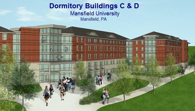
Architecture:
Situated on the south-west corner of Mansfield University’s campus, Buildings C and D are going to add a variety of living options for University students. These two dormitory buildings are to have a traditional look with a brick and stone block façade. Both buildings have two sections that meet at an angle. There also is a glass store front façade at the core spaces which will provide a great deal of natural lighting. Building D has a third section that is offset from the other two sections and is connected with small corridor. Both buildings are orientated north – south with great views of the campus to the east and the town of Mansfield to the west. The interior of these buildings are filled with suite type dorm rooms. The core spaces are placed in the middle of each floor at the angle. All of the dorm rooms in the basement floor have been placed on the west side of the corridor where windows could still allow in sunlight.
Building Facades:
The basement and first floor façade is cast stone block with 2 horizontal cast stone accent bands. Each window has a cast stone head and sill above and below it. The second, third and most of the fourth floor have a face brick façade with two soldier course bands running above and below the windows. On the fourth floor underneath the winged section of the roof, there is a section of fiber-cement façade with a cast stone trim. Because the building is being constructed using modular units, the façade will not be structural. Behind the brick and stone façade is an air gap, 1” rigid insulation and 7/16” sheathing. The fiber cement board is directly attached to the 7/16” sheathing. There is glass store front at each of the core areas to break up the horizontal lines.
Roofing:
Both buildings have asphalt shingle roofs with felt paper underneath. The roof has wave like dormers that provide an interesting aspect. The flat parts of the roof have an EPDM membrane over rigid insulation.
Sustainability:
Both buildings will use a ground-loop heat-pump to improve energy efficiency. These buildings are not achieving any LEED certifications.
Building Statistics II
Construction
After completing Phase I of the Mansfield Dormitories for Mansfield University, the Phase II 215,000 total square foot dormitory buildings were awarded to Wohlsen Construction for at-risk construction management services. The contract was a GMP worth $39 million. The site is located on the south west corner of Mansfield University’s campus. The project consists of two different buildings that are situated on both sides of a small campus road.
The schedule of Phase II was set to begin August 18, 2012 and the first building was set to be completed by August 24, 2013 (when fall semester students arrive). The shortened schedule forced the owner to analyze alternative construction techniques. The owner decided to contract Simplex Industries to modularize the design of the dormitories. The dormitory rooms were built at their factory off site and then shipped to the site. This shortened the construction time enough to have the buildings completed on time. For every day the project ran over schedule, the CM at-risk would have to pay the days’ worth of housing fee for every student that can’t occupy their room.
A 100 ton crane set the modular units in place. Crane pads were created to withhold the weight of the crane and the units. The crane pads were incorporated into the site logistics plan that also included modular unit delivery roads. Four stories of scaffolding were used to complete the masonry façade.
Electrical
The main power supply enters the 34.5kV transformer first, and then goes into the buildings at the main electrical room located in the south end of the ground floor. The power supply is coming from the main located under Clinton Street, the western boundary of the site. Once inside the main electrical room, the power supplied through a bus duct flows into to the main distribution switchboard. This switchboard supplies 208/120V power to the rest of the building. Two bus ducts supply 3 panels on each floor, while 4-7 main feeders extend to roof for the mechanical equipment. For emergency electricity, each building has a 208/120V natural gas emergency generator. The natural gas main is located along Clinton Street.
Lighting
There are eight different lighting layouts in the student rooms of the buildings. Each room has a lighting layout that consists of 2’x2’ and 2’x4’ surface mounted fluorescent lighting fixtures. The fluorescent fixtures have electronic ballasts. The 2’x2’ fixture uses (2) 14W T5 lamps and one ballast. The 2’x4’ fixture uses (3) 28W T5 lamps and two ballasts. The bathrooms of each room have 14” round surface mounted fixture with one 32W CFL lamp. The bathrooms also have 2’ wall mounted fluorescent fixtures mounted above the mirrors. The wall mounted fixture uses (2) 14W T5 lamps.
Mechanical
The main pump room is located on the east side of the ground floor corridor. The main water source enters the buildings at the pump room. In the pump room, there are two gas fired domestic hot water heaters to supply the building with hot water. The pumping fixtures in the rooms come complete with each unit. The pumping of each room is connected to a main down the center corridor and then to the main water pumps in the pump room. The mechanical systems ATC panel also is located in the pump room. Both buildings have geothermal well fields comprised of 64 wells. The geothermal water enters into the building at the pump room and then is propelled by two water pumps to the attic. In the attic, there are 4 energy recovery units in Building C and 7 in Building D. These air handlers circulate tempertured air down chases to the floors below. Each room has their own electric heat pump to adjust the room temperature to their liking.
Structural
The structure of each building is mostly wood. The modular units are created using wood and are strong enough to support the floors above it. The foundations consist of 10 foot wide concrete footings that attach to cantilevered reinforced CMU walls. Along the central corridor of the ground floor of each building, there are spread footings integrated into the slab on grade that support the small steel frame around the ground floor modular units. In the structural steel core, concrete piers support that heavy steel frame. The structural steel pieces used in the core space are W10, W12 and W14 girders with HSS 6x6 steel columns. The girders range from 15 lbs/ft to 53 lbs/ft. All girder to beam connections are shear with optional moment reinforcement. All girder to column connections are welded-moment.
Fire Protection
There are two types of fire suppression systems. The common fire suppression system is a wet pipe quick response system with recessed pendent sprinkler heads. This system is used in all areas except the attic. The attic has a double interlock preaction system with quick response upright heads. The fire pump is located in the pump room with the other mechanical water pumps.
Transportation
There are 3 stair cases in both buildings. One stair case extends from the first floor to the fourth and the other two extend to from the ground floor to the fourth floor. These stair cases have a 2 hour fire-rating. The walls are built out of CMU block with fire rated doors at the openings. The stairs are created with two steel fabricated stringers and welded metal tread pans filled with concrete. Each building has two elevators that are located in the steel core. The elevators extend from the ground floor to the fourth floor. The elevator equipment room is located on the ground floor next to the elevators in the center of the building. The elevator shaft is also built with CMU block. The elevators are rated to carry a 3500lb load and moves 175 ft/min. Every elevator is equipped with a security camera.
Telecommunications/Security
The main distribution frame is located in the room at the south end of both buildings on the ground floor. There is room in the core of the second floor that holds the MDF for the floors above. Each room has a cable jack and data jack. The security system is located in a room on the ground floor. There are security cameras that monitor the entrances and elevators. The monitors that show current footage of the security cameras are located in each building’s office on the ground floor.
|