SOLAIRE WHEATON
LOCATION: WHEATON, MD 20902
KEVIN MARTYN
CONSTRUCTION OPTION
Image Courtesy of Washington Property Company
|
|
|
|
|
|
|
|
|
|
|
BUILDING STATISTICS PART 1 |
|||
|
|
|||
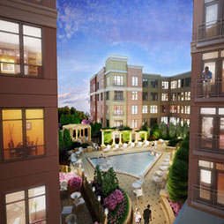
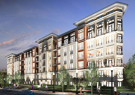
ARCHITECTURE Solaire Wheaton is an apartment building which sits on the site of a previously existing church before it was demolished. The structure consists of 209 market rate units and 29 moderately priced dwelling units (MPDU) units. Individual apartments come in a variety of layouts for studio, single bedroom, and double bedroom units. The building hosts a wide range of amenities including a landscaped courtyard on the second floor seen in the rendering at the right, as well as a swimming pool, a wifi café, clubroom, a fitness center, and a motor court entrance below the courtyard off of Georgia Avenue. |
Rendering Courtesy of The Preston Partnership |
|||
CODES - City of Gaithersburg Fire Code, Ch. 11, City Code |
||||
BUILDING ENCLOSURE |
Image Courtesy of K. Martyn |
|||
Graphic Courtesy of K. Martyn |
Image Courtesy of K. Martyn |
|||
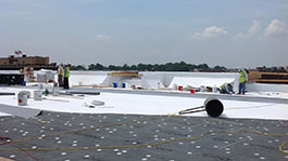
The building is capped with a flat roof system that uses a combination of interior and exterior water drainage systems. It is closed in with a thermoplastic polyolefin membrane (TPO) roof and metal coping on the parapet and canopy walls. |
||||
SUSTAINABILITY FEATURES The Solaire Wheaton project is aiming for LEED certified at the completion of the project. During the demolition phase, materials of the existing structure were diverted from landfills and recycled. The design for the new structure includes several sustainable features. The project is located in close proximity to alternative transportation, particularly the Wheaton metro station, as well as many services within the local community. In addition the building will feature preferred parking spaces for low emitting and fuel efficient vehicles. To reduce the heat island effect, the design specifies a white TPO roofing material as well as 100% covered parking areas. The irrigation system includes a series of bio retention areas which removes contaminants and sedimentation from storm water. |
||||
BUILDING STATISTICS PART 2
|
|||||
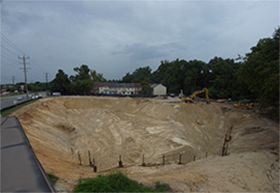
EXCAVATION & EARTH RETENTION The site required some excavation to accommodate the two story semi-below grade parking garage. Site access was at the southeast corner of the site where trucks entered to take soils off site. As seen in the photo at the right, the site could be sloped back on the east elevation towards Georgia Avenue. The geothechnical engineer recommended a small earth retention system of soldier beams and wood lagging in the northeast corner of the site also seen in the bottom part of the photograph. |
Image Courtesy of CBG |
||||
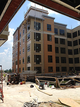
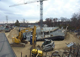
CONSTRUCTION (Means & Methods) The concrete and wood framing were installed with the help of a tower crane with a 180' jib, seen at the right. The crane was erected at the beginning of the foundations phase and was dismantled once the structure was topped out and all of the roof top equipment was lifted into place. During the concrete foundation and structure phases, concrete was placed using both crane & bucket as well as concrete pump trucks. |
Image Courtesy of CBG |
||||
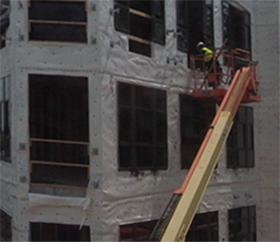
The window installation was a tedious task with over 800 opening with windows and doors to install. Windows were single, double, and triple bays and were installed using JLG basket lifts. The process for installation was flashing the opening after tyvek has been installed, cleaning the surfaces with alcohol, applying the caulk to the flanges, placing the window in the opening, leveling and plumbing the window and then fastening through the flange. This was a long process with several steps in each installation. |
|||||
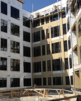
Siding was installed within the courtyard by the use of pump jacks as seen in the photo at the right. Pump jacks are 80' tall and were used in 4 part sections rotating counter-clockwise within the courtyard. The remaining exterior siding was completed by the use of JLG basket lifts similar to the window installation. |
Image Courtesy of K. Martyn |
||||
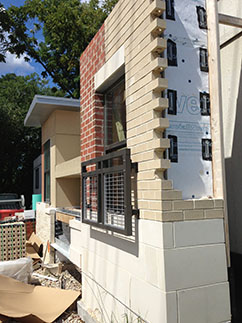
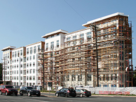
The masonry part of the enclosure includes the east and partial north elevations. The tall facade bumpouts were cladded in susquehanna stone, while the infilled areas of the facade were tan and red brick. This portion of the work was done by means of tube scaffolding. The east facade was scaffolded in two portions as seen in the photo at the right.
|
Image Courtesy of The Preston Partnership |
||||
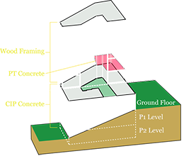
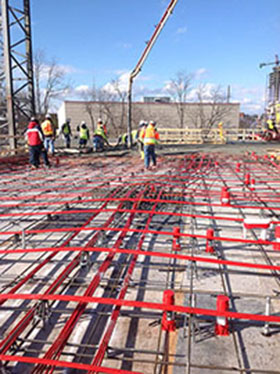
STRUCTURAL SYSTEM The foundation of the structure consists of column spread footings as well as foundation wall strip footings. The foundation walls are located on the east elevation along Georgia Avenue and the site slopes gradually to grade on the west elevation P2, the lowest level, on the west elevation. As seen in the image to the right, the northeast corner of the third floor of this structure utilizes a 10 ½” thick post tensioned concrete podium transfer slab. The PT tendons are laid out with a maximum spacing of 60”. Assumed effective strength of the tendons after all losses is 27 kips. |
3D SectionCourtesy of K. Martyn |
||||
Image Courtesy of CBG |
|||||
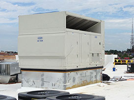
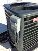
MECHANICAL SYSTEM The mechanical system for the building is separated into two separate systems. The common spaces on floors 1 through 6 are conditioned by two 50 ton packaged rooftop air handling units supplying 7500 CFM. The AHU's use direct expansion cooling and natural gas heat supply. They are located on the east and west sides of the building and are air is supplied through shafts that descend through the building along the corridors. The remaining areas of the building including apartment units and amenity areas are conditioned by split system heat pumps. Residential units are serviced by 600 and 800 CFM heat pumps respectively based on their heating and cooling load. Condensing units are located on the roof while the air handling units are hung on the wall in the units’ mechanical closet. In order to meet the Indoor Air Quality Management requirements for section 01450 of LEED, all ducts were protected during construction. |
Image Courtesy of K. Martyn |
||||
 |
 |
||||
Images Courtesty of K. Marty |
|||||
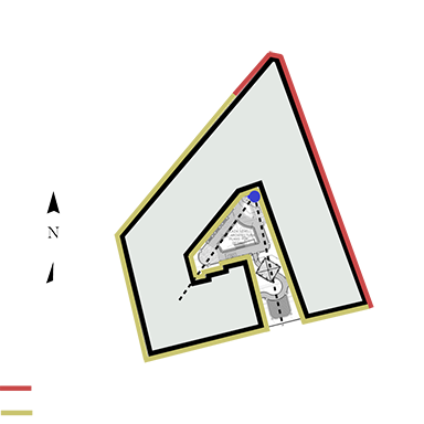
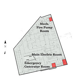
ELECTRICAL SYSTEM Solaire Wheaton uses a three phase 208/120 V electrical distribution system provided by PEPCO. Service is stepped down by two transformers located on the southeast corner of the building, adjacent to the garage entrance. The secondary distribution wires are then fed to the main electrical room located on the southeast corner on the P1 level as seen in the P1 floor plan to the right. The main electric room houses the two switchboards. Both switchboards are rated at 4000A. Switchboard 1 feeds the meter stack closets located on floors 4 and 6. The meter stack closets are located in pairs on every other floor in the southwest and northeast corners of the building. Switchboard 2 feeds the meter stack closets on floor 2 as well as the emergency power service. |
Image Courtesy of K. Martyn |
||||
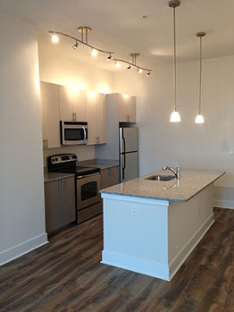
LIGHTING SYSTEM As the electrical distribution is at 208/120V, all lighting fixtures are 120V for residential occupancy. The two garage levels are illuminated by LED fixtures. LED and flourescent fixtures are used throughout the building corridors and in the amenity spaces for effiecincy and energy savings to meet LEED certified status. A combination of flourescent and incandescent fixtures are used in the units to offer more comfortability as seen in the photograph at the right. |
Image Courtesy of K. Martyn |
||||
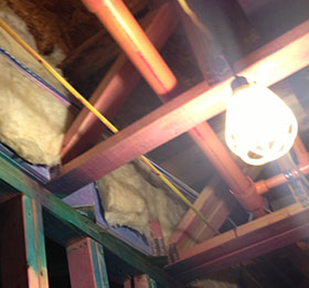
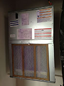
FIRE PROTECTION The building is protected by a wet sprinkler system. Steel piping was used in the garage to prevent pipe damage as it is partially exposed, while the rest of the building uses CPVC. CPVC has several advantages when alayzing the constructability as it weight much less than steel making it a less labor intensive process when perfroming overhead rough-in. As common in the construction industry, the sprinkler mains were run along the corridor and branch off to the units on either side. |
Image Courtesy of K. Martyn |
||||
TRANSPORTATION Vertical transportation is made possible by the KONE MonoSpace elevator which travels at 350 fpm. The MonoSpace elevator concept seen in the photograph to the right, was introduced by KONE in 1996 and allows for a design free of a machine room. According to KONE, this elevator design creates a superior ride quality, creates more usable space, uses less energy, reduces construction cost, and is the preferred choise for mid-rise buildings 6 to 27 floors. Within the building there is a double bank elevator in the northeast corner as well as a single bank elevator in the southwest corner. |
|||||
AE SENIOR THESIS
PENN STATE UNIVERSITY
ARCHITECTURAL ENGINEERING
AE COMPUTER LABS
CONTACT KEVIN
This page was last updated on 10-24-13, by Kevin Martyn and is hosted by the AE Department ©2014