Building Statistics: Part 1
General Building Data | |
|---|---|
Building Name | National Law Enforcement Museum |
Location | Washington, D.C. |
Occupant's Name | National Law Enforcement Officers' Memorial Fund |
Occupancy Type | Assembly (Museum) | Business (Office & Mercantile) |
Total Size | 54000 SF |
Stories Above Grade | 1 |
Total Levels | 4 |
Schedule | 28 Months |
Cost | $50 Million |
Delivery Method | Design-Bid-Build |
Dates Of Construction | June 2014-September 2016 |
Project Team | |
|---|---|
Architect | Davis Buckley Architects & Planners |
MEP | Joseph R. Loring & Associates |
Civil | A. Morton Thomas & Associates |
Structural | Spiegel, Zamecnik & Shah |
Construction Manager | Clark Construction |
Acoustic Consultant | Shen Milsom Wake |
Lighting Consultant | Claude R. Engle |
Landscape | Urban Trees + Soils |
Architecture
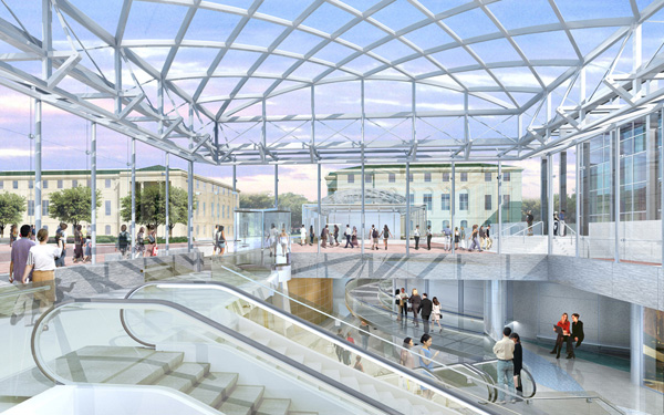
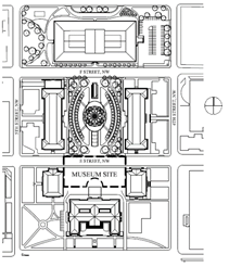
The design of the National Law Enforcement Museum (NLEM) complements the design of the National Law Enforcement Memorial located across the street in Judiciary Square in Washington DC. A full context of the site is shown in Figure 2. This design follows that of George Hadley's 1820 design for the DC Courthouse. Two glass pavilions frame the main hall of the District of Columbia Court of Appeals. These will serve as the entries and exits to the museum space which will be located in the two floors below. The decision to place the museum spaces below grade was to reduce the intrusion to the landscape. The pavilions are a more elegant solution to a standard concrete or brick building.
After entering the museum, the patrons are led down into the main exhibit gallery. The components on this floor include a gift shop, café, research & archive center and ticketing area. On the next floor below is further exhibit space. The main components of this area is the Hall of Remembrance which relates to the Memorial across the street and the entrance to the theater. The third floor below ground level is home to the central plant, Pepco Station, electrical switchgear room, fire control room and building management control room. The central plant will work in conjunction with the mechanical penthouses located in the rear portions of the East and West Pavilions.
Major codes used in the design of NLEM include: 2006 IBC, 2006 International Mechanical Code, 2006 International Plumbing Code, 2006 ICC Electric Code, 2006 International Fire Code, 2003 Accessible & Usable Buildings and Facilities, 2010 ADA Accessibility Guidelines for Buildings and Facilities. This design uses the Underground Buildings of the IBC, Section 405.
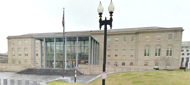
The museum is located in the SP-2 zoning district of Washington, D.C. This area is limited by height of 90 feet. Historically, the architects followed the language of the area, specifically the façade of the DC Court of Appeals shown in Figure 3. The site is also historic. Therefore, the building design was required to receive from The National Capitol Planning Commission, the State Historic Preservation Office, the DC Preservation Review Board, the United States Commission of Fine Arts and the Advisory Commission on Historic Preservation.
Building Enclosure
As the showpiece of the design, the East and West Pavilions are completely framed in the same glass curtain wall type material. This exterior glazing is either flat or curved insulated low-iron glass. Framework between the glass panes are of stainless steel and aluminum components. To further manage daylight and solar radiation, the South and West walls of the pavilions use two elements to reduce excess heat gain. The lower eight feet utilize a fabric mesh to prevent further solar gain while the upper two feet of west and south pavilion walls have louvers that may be adjusted to prevent too much sun from infiltrating the museum space.
Sustainability Features
The National Law Enforcement Museum has established this project will achieve LEED Silver Certification using a number of strategies. This project will use recycled content as much as possible, harvest materials within 500 miles of the site and will also reduce its indoor emissions. Other sustainable strategies include creating and executing an Indoor Air Quality Management Plan, managing construction waste by diverting 75% of waste from landfills, meeting energy performance criteria, controlling site erosion and sedimentation, and reducing the chlorofluorocarbons according to the Montreal Protocol. Appendix A contains the LEED Scorecard from the specifications.
Building Statistics: Part 2
Primary Engineering Systems
Construction
The National Law Enforcement Museum is a design-bid-build project. Davis Buckley Architects & Planners worked closely with the National Law Enforcement Officers Memorial Fund to design the museum. They then acted in proxy with the owner to select the engineers and construction manager. The estimated total cost for this structure is $50,000,000. The construction schedule is set for 28 months beginning June 2014 and ending in September 2016.
Electrical System
Electricity is supplied to the museum by PEPCO whose substation will be in the central plant. The supply is tapped from the main line that runs underneath E Street NW with two 13.2 kV feeders connecting to two 1500 kVA dry type transformers. The lighting system within the building is 480/277 V and other components use 208/120 V.
Lighting System
Claude R. Engle is the lighting consultant for this project. The exhibit spaces utilize LEDs and PAR lamps. The theater is designed with a combination of PAR lamps, halogen lamps and LEDs. Adjacent spaces use fluorescents and LEDs. The power consumption is balanced using a building Power Monitoring System (PMS).
There is significant use of daylighting in the space which is balanced with the interior lighting using the Power Monitoring System. The pavilions, being mostly glass, provide large amounts of daylighting for the pavilion and ticketing level. Some light also permeates into the exhibit level.
Mechanical System
Air handling units & their zones, heat type, cooling type, fan coil units, control The museum is ventilated using six air handling units supplying variable air volume boxes in building areas as specified below. Auxiliary fan coil units will other important spaces, also shown below.
Unit Name | Location | Area Served |
AHU 1 |
Penthouse - West |
West Entry |
AHU 2 |
Penthouse - East |
East Entry |
AHU 3 |
Ticketing - West |
Exhibits |
AHU 4 |
Ticketing - East |
Exhibits |
AHU 5 |
Ticketing - East |
Theater |
AHU 6 |
Central Plant |
PEPCO Substation & Switchgear Rm |
FCU 1 |
Ground - West |
Hoover Research |
FCU 2 |
Ticketing - West |
Elev. #2 Control |
FCU 3 |
Ground - East |
Fire Control |
FCU 4 |
Ticketing - West |
Café 221 |
FCU 5 |
Ticketing - West |
West TVS Lobby |
FCU 6 |
Ticketing - West |
Gift Shop |
FCU 7 |
Exhibit - East |
AV Room 3201.2 |
FCU 8 |
Exhibit - West |
Exhibit AV 317 |
FCU 9 |
Central Plant |
Elev. #1 Control |
FCU 10 |
Central Plant |
Elev. #3 Control |
FCU 11 |
Central Plant |
Building Control |
FCU 12 |
Ticketing - West |
Food Service |
FCU 13 |
Ticketing - East |
Warming Kitchen |
FCU 14 |
Exhibit - East |
IT Closet |
FCU 15 |
Exhibit - East |
IT Closet |