PART I
General Building Data
Building Name |
Location |
Building Occupant |
Occupancy |
Size |
Number of Stories Above Grade |
Dates of Construction |
Total Construction Cost |
Project Delivery Method |
|
Morton Hopsital Expansion
Taunton, MA
Steward Healthcare
Hospital
The addition alone is 40,000 SF while the existing building
is 100,000 SF
A 1-story addition connected to the existing 2-
story building.
Construction Documents were completed and approved at
the end of July 2014. The construction start date is
unknown at this time, however the schedule indicates a
16-week duration for phase 1, and a 40-week duration for
phase 2 of the addition.
$23.1 Million GMP
Design-Build
|
Architecture
Morton Hospital is currently a 100,000 SF 2-story above grade hospital that provides services including emergency and expressMed care, cardiology, orthopedics, maternity, and Outpatient surgery. Recently being named a “2013 Top Hospital for Quality and Patient Safety” by The Leapfrog Group, Steward Healthcare has decided to expand to suit its growing demands.
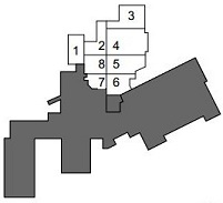
As proposed, the addition at Morton Hospital will be split into a two phase project. The first phase includes the MRI addition while the second phase houses the Emergency Department. It will be built around an existing covered parking area which will be fit out for interior space. The MRI will be relocated into a new building and opened while the ED is still under construction. Phase two includes not only the emergency department, but also a Psych Ward, imaging suite, various treatment and triage rooms, as well as decontamination and isolation rooms. These various spaces demand high indoor air quality and differing safety needs, creating a challenge for the mechanical engineer in the system selection and air distribution throughout the spaces.
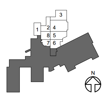
As seen above, the Phase 1 expansion is the boxed out grey section directly in the middle, Phase 2 expansion is in white, and the exisiting hospital in the remaining grey. The addition will be accessed from the existing building as well as through multiple exterior entryways including an ambulance entry vestibule and emergency room vestibule. Roof slab construction is anticipated to house as a floor slab for possible future construction.
(images pending)
Historical requirements: not applicable
National Codes:State Building Code of the Commonwealth of Massachusetts, 8th edition
Zoning: Not available at this time
Building Enclosure
The building facade will include a brick veneer and composite metal panel system. An aluminum storefront system will be employed, and includes a tinted 1 inch insulated glass and insulated opaque spandrel glass. (image pending)
Roof slab construction will be anticipated to house possible future construction as a floor slab. A light colored TPO membrane roof over a rigid polysio insulation on a concrete and metal deck slab with two hour rated construction will be utilized.
Sustainability Features
Morton Hospital Expansion employs the use of continuous thermal insulation with a maximum U-value of U-0.050 to ensure thermally consistent interior spaces. Additionally, occupancy sensors are provided in hospital offices for both lighting control and temperature control.
PART II
Construction
Morton Hospital Expansion was designed using a design-build method and employed a construction manager who was awarded the job under a guaranteed maximum price contract. A separate construction cost is provided for both phases of the project. Phase 1 comes to a total of $2 million, and $790/SF, while Phase 2 comes to a total of $21.1 million, and $560/SF, totaling $23.1 million for the whole project and averaging at $577/SF. Currently, the construction start date is unknown, but Phase 1 has a schedule of 16 weeks and Phase 2 has a schedule of 40 weeks. Both Phases will begin at the same time, and Phase 1 will open while Phase 2 remains under construction.
Mechanical
The primary source for the building addition heat and chilled water is provided by the existing hospital steam system and chiller plant. The low pressure steam system will employ heat exchangers to provide building reheat, preheat, perimeter heating, and domestic water heating. Chilled water will be provided by both the existing hospital distributed chiller plant as well as a new 155 ton air cooled chiller. Both steam and chilled water connections will originate from the existing basement below the proposed MRI space.
The central air handling system will be provided by two modular air handling units. Phase 1 will be provided by a rooftop packaged DX unit containing a steam preheat coil and direct expansion cooling coil, provided by existing steam plant and air cooled condensing unit respectfully. Phase 2 will employ a roof mounted chilled water air handling unit containing a hot water preheat coil and chilled water cooling coil, supplied by a steam-to-water heat exchanger and air cooled chiller respectfully. Both will be variable air volume, supply return type, controlled by minimum outside air monitoring and airside economizer control. Humidifiers are included within the units, and supply and return fans are driven by variable frequency drives.
Electrical
An outdoor transformer converts 13.8 kV to 480/277 V and distributes power to a 1600 A switchgear, supplying power to two 3 phase, 4 wire distribution panels. The first distribution panel supplies power to the lighting panel. A transformer converts the 480/277 V to 208/120 V for and supplies the mechanical equipment panels. A diesel 625 kVA emergency generator supplies power to the 480/277 V emergency switchboard.
Lighting
Both fluorescent and LED fixtures are used within the building. The majority of fixtures are set at a correlated color temperature of 3500K. A high CRI is recommended in order for doctors and physicians to properly operate on or analyze patients’ symptoms. All of the fixtures are set at a CRI of at least 80. An inverter is used to convert AC to DC power, in order for LED lights to utilize an electronic dimming driver.
Structural
The Morton Hospital expansion project structural system was designed to accommodate snow, wind, and earthquake loads designated by the Commonwealth of Massachusetts State Building Code. The lateral force resisting system is steel moment frames on the exterior of the building. The foundation is a 5 inch slab on grade with 24”x24” grade beams. Beneath the MRI, a 10” slab on grade is utilized with 24”x24” grade beams to account for the excessive dead load of the required equipment. Grade beams are used to transfer loads to concrete footings. The roofing system consists of a 2-1/2 inch light weight concrete fill on a 3 inch 20 GA metal deck with an additional housekeeping pad for both air handling units. This pad is 5” thick with #4 top bars at 12” o.c. and #3 bottom bars at 12” o.c. reinforcing. Because of possible future expansion vertically above this addition, the roof slab was constructed to function as a floor slab. Both the floor and roof slab assemblies are 2 hour rated construction.