General Building Data
Building Name |
Cardinal Wuerl North Catholic High School |
Location & Site |
1617 Route 228, Cranberry Township, PA, 16066 |
Building Occupant Name |
Catholic Diocese of Pittsburgh |
Occupancy/Function Type |
Educational - E |
Size (total square feet) |
177,129 GSF |
Number of Stories Above Grade/Total Levels |
2 above grade, 1 partial below grade (Cafeteria) |
Dates of Construction |
June 2012 - June 2014 |
Overall Cost |
$70 million |
Project Delivery Method |
Design-Bid-Build; Multiple Prime GC Lead w/ CM Agency |
Primary Project Team
ARCHITECTURE
Design & Functional Components
The various roof levels and irregular perimeter shape display the complexity of the interior spaces. All of the interior spaces were split up amongst 7 sections (A-G) based on the types of rooms that are in that area.
Area A is split amongst two levels on the south elevation of the building. The bottom level is the only area of the building that is below grade and is a partial floor. It houses the cafeteria, kitchen, and MEP rooms. The ground level of Area A boasts a 1,500-person capacity gymnasium and locker rooms.
Area B is located to the east of Area on the ground level. A maintenance room, fitness center, and athletic/administrative offices are located here.
Area C is the chapel and is located in the courtyard of the building. It branches off to the west from the main corridor between Areas A & D. The design for Area D was late and did not begin until August 5, 2013.
Area D contains the 1,000-person capacity Auditorium and more administrative areas, as well as four bathrooms. Area D is further north of A and B (which are side by side) and the main façade of D is visible from the East & West Sides of the building. Area D also has the highest roof in the building at the stage area of the auditorium. This area is called the fly tower and reaches 53’-4” above the ground level.
Area E encloses the library as well as various musical education spaces. It is located at the north east section of the building and just north of Area D.
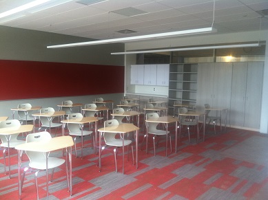
Area F is a two-story classroom wing to the west of areas A, B, D, and E and stems off perpendicularly at the intersection of Areas D & E. It contains language arts, art education, science labs and religious education classrooms. The second floor corridor has a curved ceiling that reaches up to the North clerestory and reflects light down into the hallway as if from an omniscient source, rendering itself one of the most unique architectural features of CWNCHS.
Area G has the same functionality as Area F, in that it solely contains classrooms and is two stories tall. It contains English, health, theology, math, and social studies rooms. Area G is only connected to Area F and bends off of the West End of F towards the Southwest at exactly 27 degrees. The second level of G is being built as a core-and-shell package since the space isn’t necessary for the 2014-2015 school year. This has implications for the construction of the social studies and math classrooms only.
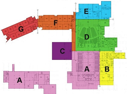
Figure 1: Building Component Diagram (Property of Astorino)
There are a few other facts and features of Cardinal Wuerl North Catholic High School that should be highlighted:
- 27 Classrooms
- Bell Tower on Southeast side with refurbished bell from original North Catholic HS
- Chapel in Courtyard
- Possible future grotto in southwest
- LEED Silver upon completion with 53/110 points
Major National Model Codes
- 2009 International Building Code
- 2009 International Mechanical Code
- 2009 International Plumbing Code
- 2009 International Energy Conservation Code
- National Fire Protection Association (NFPA) 70 – 2008 National Electric Code
- 2009 International Fire Code
- 2009 International Fuel Gas Code
- 2009 International Wildlife-Urban Code
- 2009 International Performance Code for Buildings and Facilities
- 2010 ADA
Accessibility Standards
- 2009 International Code Council/American National Standards Institute (ANSI) A117.1 – 2003 Accessible & Usable Buildings & Facilities
- Chapter 11 – 2009 IBC
- Appendix E – 2009 IBC
Zoning
This non-public education institution sits on 65 acres of property in the Cranberry Township R-1 - Rural Residential Zoning District. North Catholic was deemed Type IB & IIB Construction due to its steel frame and steel beam/deck roof structure. The Cranberry Planning Advisory Commission approved the project on May 7, 2012 and the Board of Supervisors approved the building on June 28, 2012.
Historical Requirements
Four stained-glass panels from the original North Catholic High School (also located in Pittsburgh) will be moved from the old school to the newly constructed chapel. These panels will not be a part of the building exterior for preservation/weathering reasons but they will be mounted inside each of the four non-storefront windows on the chapel. Also, the original bell from North Catholic High School is to be refurbished and installed in the new bell tower at CWNCHS.
BUILDING ENCLOSURE
Building Facades
There are three primary materials that the building façade consists of; brick, insulated metal panel, and glazed windows held in place by dry-glazed, thermal aluminum frames. The primary building envelope from inside to out is GWB, metal studs, exterior sheathing, spray-applied vapor barrier, rigid insulation, air cavity and brick veneer. There are a few variations of the brick veneer construction throughout the building. At the southern wing wall on the west end of Area G there is brick veneer wrapped around both sides of 8” CMU (typical for all wing walls). The wall construction at the chiller yard on the outside of lower level of Area A is 12” CMU bonded with 4” brick composite wall that is finished with a precast stone cap. The insulated metal panel finish conceals metal studs, exterior sheathing, and spray-applied vapor barrier or bare CMU. These insulated metal panels arrive to the site prefabricated with rigid insulation attached to their unexposed side.
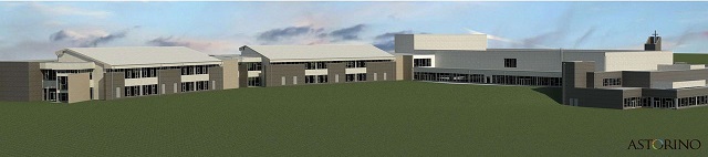
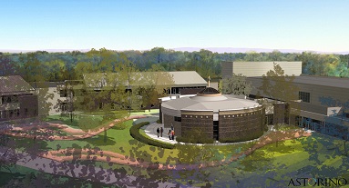
Figure 2: Southwest Rendering (Property of Astorino)
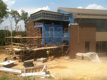 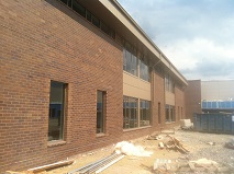 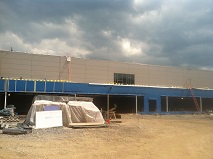
Figure 3: Construction Progress Photos (Property of Mascaro Construction)
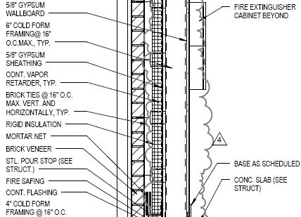
Figure 4: Typical Classroom Wall Section (Property of Astorino)
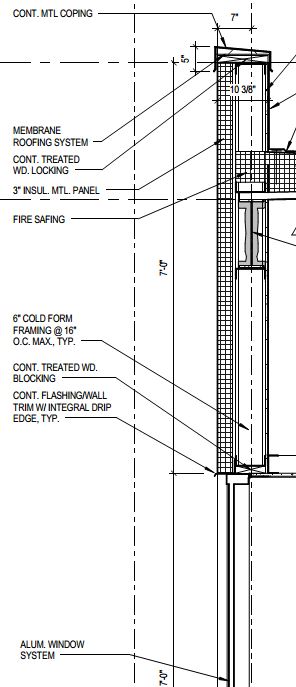
Figure 5: Insulated Metal Panel & Window System Wall Section in Main Corridor D100 (Property of Astorino)
Roofing
There are two primary types of roofing used on this project. TPO (thermoplastic polyolefin) single-ply roofing is the primary roofing system used throughout the building. The TPO extends everywhere on the roof including the parapet caps, MEP/structural penetrations, roof curbs, and everywhere where there isn’t a standing-seam metal roof. The typical detail for the TPO roofing shows a 3” layer of rigid insulation resting atop the roof deck, to which the TPO roof membrane is mechanically adhered. The other roofing system used is a standing-seam metal roof located in areas F & G. It is only located on the South parts of these building sections. As the north part of the standing-seam starts to slope upward towards the north elevations of F & G, it is abruptly cut off and a clerestory window/wall plunges downward towards the flat TPO roof. The clerestory overlooks the corridors in the second level of F & G. Since some of the roofs are not very tall in height, roof screens are installed around some of the air-handling units on the roof. Roof screens are used in a total of 3 locations around the south perimeter of the low roof. This is an attempt to preserve the aesthetic features of the façade materials by shielding large mechanical equipment.
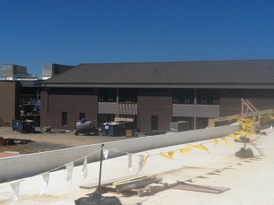
Figure 6: Standing Seam Metal Roofing Photograph from Main Corridor Roof on Area F (Property of Mascaro Construction)
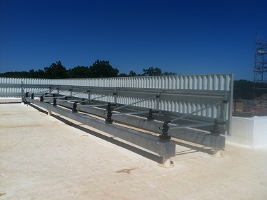
Figure 7: TPO Roofing & Roofscreen Photograph taken from Area B Roof (Property of Mascaro Construction)
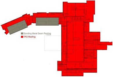
Figure 8: Roofing Material Diagram (Property of Astorino)
SUSTAINABILITY FEATURES
Cardinal Wuerl North Catholic High School is currently on track to receive a LEED Silver Certification (53 points out of a possible 110) through many trailblazing efforts that are unique for a high school under new construction. The extensive thermoplastic polyolefin (TPO) roof system helps to reduce the heat-island effect by having a high reflectivity and emittance. An extensive effort was put into place to reduce the use of high-VOC materials as well as increase the use of regional materials (within 500 miles).
In addition, FSC-accredited & certified wood was used throughout the project for items such as casework and acoustic wall panels. In another effort to increase the indoor air and lighting environment, the design implemented operable windows, advanced heating/cooling controls, the use of MERV-14 main filters and MERV-8 pre-filters, and abundant natural daylighting. In addition to the large windows, some classrooms have windows between rooms in the corner intersecting and perpendicular to the windows. This allows daylight sharing and for dark corners to receive optimum daylighting. Also, 75% or greater by weight (tons) of the waste generated on site will be recycled.
PRIMARY ENGINEERING SYSTEMS
Construction
Cardinal Wuerl North Catholic High School is being delivered as a traditional design-bid-build project. Despite the design-bid-build designation, construction experts were called in early in the design phases which created a hybrid Integrated Project Delivery environment. The owner chose a multiple prime (GC lead) with CM agency project structure based on his past experience with this delivery method. BIM is planned to be used on this project from the preconstruction phases all the way through the life of the building by the use of a facilities management model. Earthwork and site clearing were the focuses of construction early on in the project. The extensive tree clearing and excavating that needed to occur drove the project during Summer 2012. Temporary excavation support (shoring & rigging) was needed during excavation due to reported groundwater and the possibility of landslide due to excessive redbed soil. Onsite roadwork and earthwork resulted in a change of site entrance/exit several times. Parking areas were static but material laydown areas and interior access points evolved on several instances. Finally, the second floor in Area G was delivered as a core & shell package due to lack of enrollment to fill the extra space. This can be explained by expansion of facilities. A 4D Construction Model can be shown below (provided by Mascaro Construction; property of Astorino).
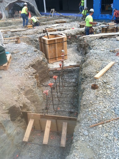
Figure 9: Construction of Chapel Footers & Column Piers (Property of Mascaro Construction)
Electrical/Lighting
An underground electrical utility service enters the building at the south side in the mechanical yard into the utility transformer. The primary service power then travels to an exterior current transformer cabinet and inside the building to the 3,000A main switchboard. Power is distributed from here to the 42-208/120V & 32-480/277V panelboards. EMT conduit runs the length of the building, feeding power to the entire complex. Classrooms utilize pendant linear fluorescent lighting while the auditorium utilizes 6” pendant LED downlights. There is a diesel generator in the mechanical yard of the building, which serves emergency power and is equipped with optional standby power. Branch electrical and IDF rooms are located in various areas throughout the school. The main electrical room is located in the southeast corner of lower Level A.
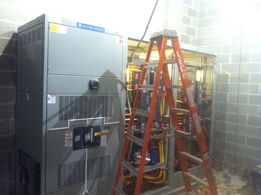
Figure 10: 3,000A Main Switchboard (Property of Mascaro Construction)
Mechanical
Cardinal Wuerl North Catholic High School is cooled by eleven VAV rooftop air-handling units, two fan coil units and thirteen split system air conditioners. The primary method of cooling spaces is by providing chilled water to the AHUs, utilizing the chilled water coil in the unit, and delivering conditioned air through overhead ducts at traditional grille, register & diffuser terminals. The aforementioned air-handlers range in size from 5,000 – 25,000 CFM and serve the library, music suite, lower level, administration areas, athletic suite, academic wings, auditorium & gymnasium. All chilled water to these units is returned to the three B&G 1510 36 Model chilled water pumps located in Room A006 (MEP) and are rated at 450 GPM (25-HP; one of these CHWPs must be on standby at all times). From here, the 30% propylene glycol chilled water passes through a glycol fill station and recirculates through one of two chillers (310/364 ton capacities) in the mechanical yard on the south side of the building. The majority of the chilled water supply feeds the rooftop AHUs but a small portion is delivered to the two fan-coil units for the purposes of providing conditioned air to the academic wing stairwells. Aside from the water-to-air system described, thirteen split system air conditioners are installed at roof level to serve MEP/MDF/machine rooms on lower level A, electrical/IDF rooms through Areas B, E, & F, and the auxiliary/storage rooms (D103/D104) in the auditorium. The SSACs used in CWNCHS supply either 240, 345, or 640 CFM and are necessary to provide constant volume air conditioning to these critical spaces.
The rooftop air-handling units also provide heated air through means of natural gas and deliver conditioned air through overhead ducts at traditional grille, register & diffuser terminals. The natural gas service enters North Catholic at the south end of the building in the chiller yard from a 3” pipe at 2-psig/8,702 cfh. The service feeds the eleven air handling units and the three water heaters through branch piping from this single entrance. The natural gas is used as fuel for the AHU’s at a max gas inlet pressure of 14 in-wg in each unit and the natural gas burner shall be fully modulating with a minimum turndown ratio of 10:1. Additional heating devices are used such as electric baseboard heaters in the main hallway and cafeteria to minimize heat loss through the large windows, unit heaters in the main MEP rooms to make sure all equipment is kept at an appropriate operational temperature and electric wall heaters in stairwells/vestibules.
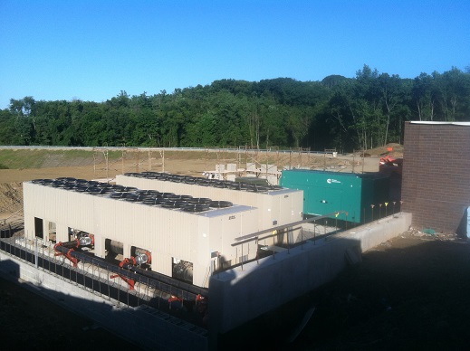
Figure 11: Chillers & Diesel Generator shown in Mech. Yard (Property of Mascaro Construction)
Structural
By utilizing a system of W10, W12 & various HSS columns, the steel skeleton supports 5” composite slabs in areas A, F & G as well as TPO/standing seam metal roofing systems. CWNCHS utilizes shear walls in the stairways & elevator shafts as well as moment connections on beams throughout the structure for lateral strength. A Linkbelt Model #LS-218H and a Terex Model #T-560 navigated the site between November 11th, 2012 and December 17th, 2012 for structural steel erection. Crawler cranes were utilized due to the large footprint of the high school. Since most of the school is on one level, a majority of the concrete flooring was poured on grade (5”). It took approximately 9 months to complete from the first pour in November 2012 to the last in August 2013. More SOG placement will occur in the chapel during Fall 2013/Winter 2014. Mascaro self-performed all concrete which included footers, retaining walls, slab-on-grade, slab-on-deck, cast-in-place stairs, prefabricated steel pan stair cast-in-place concrete, etc. Where it was necessary, the primary formwork used was lumber. Formwork was not necessary in an abundance of the SOG area due to the two courses of CMU on the footers. These CMUs shaped the outer edge of the cast-in-place slab on grade. Power buggies were used for all 1st level concrete placement while a concrete pump truck was necessary for composite slab-on-deck pours at higher elevations. Shallow foundations such as footings & grade beams were used as well as an additional 48 caissons on the north side in Areas E, F & G.
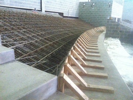
Figure 12: Auditorium Riser Seating Construction (Property of Mascaro Construction)
ENGINEERING SUPPORT SYSTEMS
Fire Protection
North Catholic uses a wet-pipe sprinkler system. Automatic sprinklers are attached to piping containing water, which is connected to the water supply through the alarm valve. Water discharges immediately from sprinklers when they are opened. Sprinklers open when heat melts the fusible device or destroys the frangible device. A 4” water service enters at the SE end of CWNCHS in the mechanical yard. Piping splits off into 5 branches that serve the different zones of the building show in the diagrams below. A sixth branch (shown in red) exits the building to Lower Level A to a 4” x 2 ½” x 2 ½” fire department connection.
.png) .jpg)
Figure 13: Diagrams showing FP System Zones and their branch division at the service entrance (Property of Alec Astorino)
Transportation
Cardinal Wuerl utilizes two hydraulic elevators. A 2,500 lb. elevator travels at 150 FPM between the first floor of Area F and the second floor. This allows access to the second story of the building, which is located in the classroom wing. Another hydraulic elevator rated at 4,500 lbs. and 125 FPM serves Area A between the cafeteria and the upstairs main corridor. A heavy elevator transit system is not required since most of the building is located on grade. Cast-in-place concrete stairs are used between the cafeteria & the main corridor on the first floor and between the main corridor & the landing of the upstairs classroom wing. Prefabricated steel pan stairs are installed in-between areas F and G and at the end of Area G in order to achieve multiple points of egress for fire safety and ease of access to/from the second story. Each pan was filled with cast-in-place concrete at 3,000 PSI.
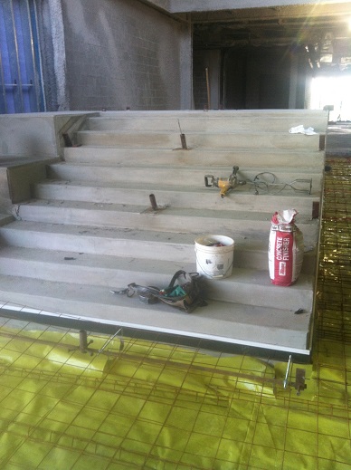
Figure 14: Recently Poured & Finished F11 Staircase (Property of Mascaro Construction)
Telecommunications, Data & Security
Specific information regarding these systems has been withheld at the request of the owner.
|