Hospital Patient Tower |
|---|
East Coast, U.S.A. |
Matthew Peyton |
Structural Option |
|
|
|---|
General Building Statistics |
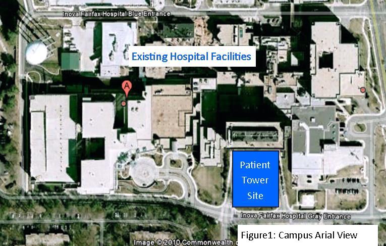
Campus Arial View |
|---|
Code
Zoning
Historical
|
|
||||||||||||||||||||||||||||||||||||||||||||||||||
|---|---|---|---|---|---|---|---|---|---|---|---|---|---|---|---|---|---|---|---|---|---|---|---|---|---|---|---|---|---|---|---|---|---|---|---|---|---|---|---|---|---|---|---|---|---|---|---|---|---|---|---|
Façade Detail 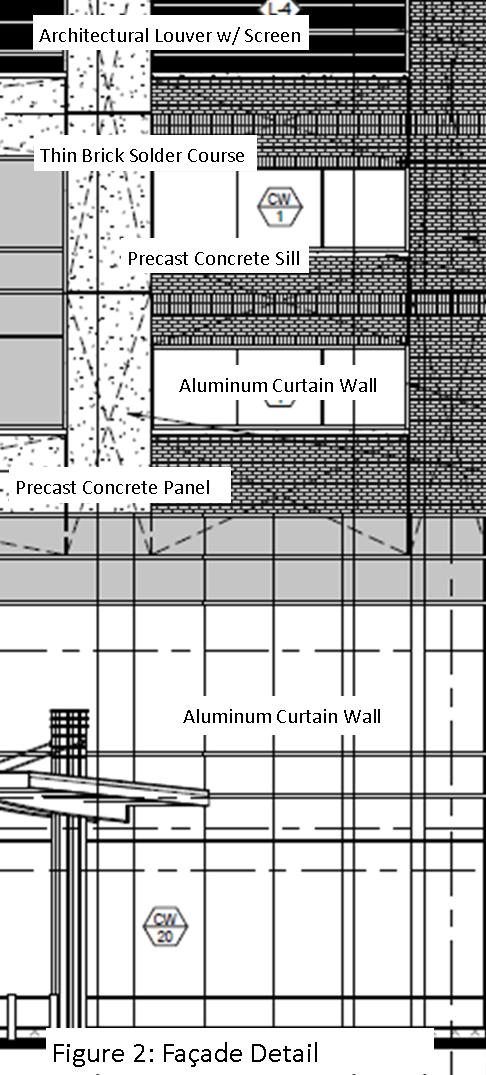 |
|
||||||||||||||||||||||||||||||||||||||||||||||||||
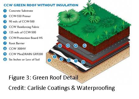
Living Roof
|
The main roof system that can be found on the majority of the building’s roof area is a POLYVINYL-CHLORIDE (PVC) ROOFING board placed on top of metal deck or concrete slab and is then followed with insulation board. Walkway Roof Pavers are placed in areas of traffic on the roof to protect the insolation board.On the second floor roof area there is a Living Roof 4” deep system (Figure 3) that can be accessed but patients and visitors of the tower. | ||||||||||||||||||||||||||||||||||||||||||||||||||
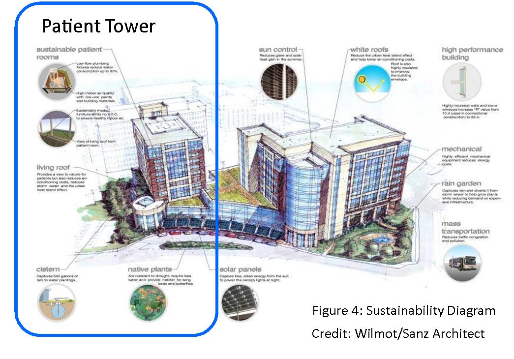
Sustainability Features The design of the Patient Tower includes many environmentally sustainable aspects and is seeking Silver Certification from the Leadership in Energy & Environmental Design (LEED) building certification system. Patients will see elements such as a "green" roof, water cisterns and rain gardens. The design also incorporates a highly efficient energy system and insulation, as well as paints, carpets and furniture with low or no volatile organic compounds (VOCs). The tower will also will use low-flow plumbing in an effort to dampen its effects on the environment. See Figure 4. |
|
||||||||||||||||||||||||||||||||||||||||||||||||||
Mechanical System The Patient towers mechanical systems are centralized on the 5 floor of the tower which is reserved for mechanical systems. The air conditioning for the tower is controlled by 5 fan cooled AC units that are located on the 2nd floor roof these units are then connected to heat exchangers with in the building. For the towers heating source there are 4 steam boilers that will then distribute steam thought out the building to heat exchangers. All of these mechanical systems are run in the 5 mechanical chance ways that run out from the 5 floor. The Stairwells are equipped with are 10000 CFM fax to maintain pressurization. Electrical/Lighting System There are two 2000KVa transformers that are used to provide the power to the Patient tower from the local department of power. Since there will be critical care patients in this tower, the main power is backed up with a 2000KW generator feeding a 2000 KVA transformer. The lighting system is a 480/277V system with mainly Fluorescent lighting and some special lighting where needed. The Tower has both a 480/277 and a 240/120 electrical system that run thought out to allow the powering of the different equipment that is used in a hospital setting. Fire Protection System The Towers structural system is concrete so there is no need for the addition to a fire protective coating. As an active fire protective system the tower included an automatic sprinkler system. Building Transportation The transportation in the tower will be guided by the central stairway and the 6 elevators. Three are designated for visitors and the other three are designated for patient and staff use. |
|
|
| User Note: While great efforts have been taken to provide accurate and complete information on the pages of CPEP, please be aware that the information contained herewith is considered a work-in-progress for this thesis project. Modifications and changes related to the original building designs and construction methodologies for this senior thesis project are solely the interpretation of Matthew Peyton. Changes and discrepancies in no way imply that the original design contained errors or was flawed. Differing assumptions, code references, requirements, and methodologies have been incorporated into this thesis project; therefore, investigation results may vary from the original design. |