
for Review
04.28.12 Thesis Reflection Posted
04.28.12 Thesis Research Posted
04.28.12 Final Presentation Slides
Posted
04.04.12 Final Report Posted
03.25.12 Presentation Outline Posted
03.25.12 Sample Slides Posted
01.27.12 Revised Thesis
Proposal Posted
01.26.12 Question Posted to
Discussion Board
01.16.12 Building Statistics Part
II Posted
01.12.12 Proposal Revision Posted
12.15.11 Thesis Proposal Posted
11.18.11 Technical Report 3 Posted
10.24.11 Thesis Abstract Posted
10.19.11 Technical Report 2 Posted
09.23.11 Technical Report 1 Posted
09.12.11 Building Statistics Part I Posted
09.08.11 Owner Permission
Form Received
09.08.11 Student Biography Posted
08.26.11 Building Statistics Draft

Building Statistics Part I:
General Building Data:
Building Name: Inova Fairfax Hospital - South Patient Tower
Building Location: Falls Church, VA
Building Occupant: Inova Fairfax Hospital
Building Function: Hospital/Patient Tower
Size: 236,000 ft2
Number of Stories: 12 stories above grade + Penthouse (1 story below grade)
Height: 170’-2”
Dates of Construction: Summer 2010 - Fall 2012
Project Cost: $76 million
Project Delivery Method: Design-Bid-Build
Owner: Inova Fairfax Hospital
General Contractor: Turner Construction
Architect/Planner: Wilmot/Sanz Architects
Structural Engineer: Cagley & Associates
MEP: RMF Engineering, INC.
Civil Engineer: Dewberry & Davis LLC
Wilmot/Sanz Architects designed the South Patient Tower as a continuation of the main architectural features of the existing patient tower building (Figure 1), while at the same time displaying Inova's commitment to sustainable and functional buildings. Consisting of 174 all-
private intensive-care and medical/surgical patient rooms, the floor plans are situated so that the various intensive-care unit specialties correspond to the same level as that of the existing main hospital. In order to meet the patient's specialized needs, workstations will be placed outside of
the patient's rooms to keep the privacy theme while monitoring the patients at the same time.
Major Codes:
International Building Code 2006
Virginia Uniform Statewide Building Code 2006 (Supplement to 2006 IBC)
ASCE 7-05
ACI 318-05
Zoning:
Fairfax County Zoning Classification: C-3
Inova Fairfax Hospital Campus Development Plan
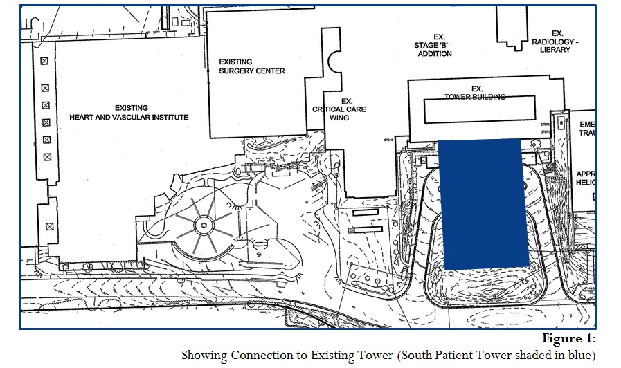
As an early phase in the Inova Fairfax Hospital Campus Development Plan, the South Patient Tower will be connected to the existing patient tower at all levels above grade (including the penthouse). Along with the physical connection, the architecture of the South Patient Tower
shares some similarities with the surrounding campus/hospital buildings.
Facade:
The facade is largely composed of a smooth finished precast concrete panel as
well as a precast concrete panel with a thin brick face. To add more architectural detail, thin brick soldier courses are used at the story levels (starting at the 4th floor). The first two levels are composed entirely of an aluminum curtain wall system which is also used
for the majority of the building's windows. Two main architectural features stand out
along the ground floor of the building, the large two-story rotunda and the canopy
covering the main entrance which is constructed from 4 custom steel columns.
Roofing:
The roofing system on the 11th floor is comprised mainly of POLYVINYL-CHLORIDE (PVC) roofing situated on top of Composite Polyisocyanurate Board Insulation.
This system rests on top of a metal deck system or a concrete slab (depending on the location). Highlighting the 11th floor roof is the pre-engineered aluminum helicopter
landing system. Supporting the landing platform is a system of structural steel columns with vibration isolators. The main design features of the lower roof level (2nd floor)
consist of a vegetated roof system, accent vegetation and concrete roof pavers.
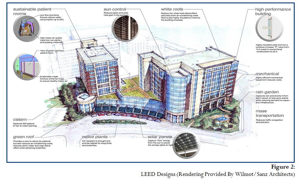
The South Patient Tower is attempting to achieve LEED Silver Certification by including
numerous sustainable designs (Figure 2). Inside the patient rooms, the use of low-VOC paints, building materials and furniture lead to a higher indoor air quality. Also, the use of low flow plumbing fixtures and sensors greatly reduce the water consumption (by up to 30%). Outside
of the building, native plants that are resistant to drought surround the building. From the
patient rooms, guests will be able to see the green roof and the water cisterns used to capture
rain water.
Top of Page
Building Statistics Part II:
Structure:
Schnabel Engineering North performed the geotechnical studies for the South Patient Tower
(SPT) and provided the report in which they explain the site and below-grade conditions. The structural engineers of Cagley & Associates designed the foundation for an undisturbed soil net allowable bearing pressure of 3000 psf. In light of the soil conditions, the SPT utilizes a
foundation with a system of 16 in. diameter auger-cast piles and pile caps on top of a 5 in. slab
on grade. Due to higher stresses around the staircase and elevator pit, a large pile cap is situated around each of these areas to help alleviate the stresses on the slab.
Moving up the structure, the main superstructure is composed of a 9.5 in. two-way flat slab concrete system. A drop panel is located at every column location in order to prevent punching shear as well as to increase the thickness of the slab to help with the moment carrying capacity
of the slab near the columns. The typical column size is 24 in. x 24 in. with bay sizes relatively constant throughout the structure at 29 ft x 29 ft.
Shear walls and ordinary moment resisting frames make up the main lateral force resisting
system in the South Patient Tower and are situated throughout the building to best resist the
lateral forces in the building. Seven different 12 in. thick walls make up the shear wall system which surrounds both the main staircase and the main elevator while the moment frames are situated near the connection to the existing portion of the hospital and at the far end of the structure. Most span from the basement level to the main roof line, but the northern core
around the elevator shaft extends up the entire 175 ft height to the top of the penthouse level.
The moment frames are situated near the connection to the existing hospital and at the southern end of the structure with most oriented in a North-South position.
Construction:
As an early phase in the Inova Fairfax Hospital Campus Development Plan, the south Patient Tower will be connected to the existing portion of the hospital. The 236,000 ft2 concrete
structure consists of 12 stories above grade (excluding the penthouse) with an additional story below grade. The $76 million project includes 174 all-private intensive-care and medical/surgical patient rooms and is expected to be completed by Fall 2012.
Due to the connection with the existing part of the hospital, construction must not cause any delays with the existing structure. Means of weather proofing the connected areas is of crucial importance to the construction team as well as the coordination between the construction
crews and the hospital staff.
Mechanical:
Using the existing central utility plant and campus loop, steam and chilled water enter the South Patient tower through the basement level. The main storage for the mechanical equipment/units that service the entire building occurs on the fifth floor of the structure. Both the upper and
lower floors are supplied by (4) 50,000 CFM air handling units located on the fifth floor. The air for the food/kitchen areas of the tower are supplied by (2) air handling units located on the roof above the second floor of the structure. Heat for the entire building will be provided by (3) heat exchangers located in basement of the structure. Converting steam to hot water, the hot water exchangers direct the water to (3) 715 GPM pumps that serve the air handler heating coils. To distribute the air throughout the building, constant air volume units, some with reheat capabilities, supply the entire building with treated air.
Electrical:
The electricity enters the South Patient Tower through two main feeds at 34.5 kV. Once the electricity enters the building through the basement and into the electrical room, two 5,000 kVA transformers feed a double-ended main substation. Once the voltage levels drop down due to the transformers, the feeders connect to the main building switchgear which distributes the power/electricity to the various parts of the building. Two bus ducts rated for 600 A each
supply power to the patient floor levels. Transformers are situated throughout the building to
step down the voltage to the appropriate levels. Mechanical and lighting loads are fed at
480/277 V, while receptacles and other loads are at 208/120 V. Two parallel 2 MW backup generators serve the South Patient Tower with future capacity to add three additional generators.
Lighting:
Lighting fixtures predominately run at 277 V. The majority of the interior lighting is provided by
a combination of linear T8's and compact fluorescents. Typically, the patient rooms include a
2x4 recessed fixture with a combination of 40 watt TT5 bulbs and 24 watt DDT down lights.
The exterior lights used to enhance the architectural features of the facade system are mainly composed of LED fixtures. Various colors of LED lights are used to provide architectural
details around the building, including a fountain situated near the main entrance to the South
Patient Tower.
Conveying Systems:
The transportation in the tower will be guided by the central stairway and six elevators. Three
of the elevators are designed for a 7500# capacity at 350 feet per minute (fpm) and a Class “A” freight loading. The remaining three elevators are designed with the same class rating, but for 4000# at 400 fpm. All six elevators are gearless traction passenger elevators. A pair of adjacent heavy duty escalators specifically designed for public transit service (operating at 100 fpm
with 32 in. wide step treads) are located between the ground floor level and the 1st story near
the main atrium.
Fire Protection:
The fire protection system in the South Patient Tower was designed in accordance with the
IBC. The thickness of the two-way flat slab concrete system meets the UL specifications for a two-hour fire rating, and the building also relies upon the main sprinkler system which consists
of an automatic wet class 1 standpipe system. The piping for each system was designed in accordance with NFPA Standard 13 and the Hospital's Insurance Underwriter Standards. All
areas of the South Patient Tower are to be protected by the main sprinkler system.
Top of Page
Note: While great efforts have been taken to provide
accurate and complete information on the pages of
CPEP, please be aware that the information contained
herewith is considered a work in progess for this thesis
project. Modifications and changes related to the
original building design and construction methodo-
logies for this senior thesis project are solely the
intrepretation of Nathan McGraw. Changes and
discrepancies in now way imply the the original
design contained errors or was flawed. Differing
assumptions, code references, requirements, and
methodologies have been incorporated into this thesis
project; therefore, investigation results may vary from
the orginal design.
This page was last updated on on 4/28/2012 by Nathan McGraw and is hosted by the AE Deparment © 2012