|
Building Statistics: Part Two |
|
S t r u c t u r a l |
The addition to the State Rehabilitation Institute rests on a 5" concrete slab, supported by 6" crushed stone and 1.5 lbs fibrous reinforcement per cubic yard. The slab is supported at its base by grade beams and reinforced concrete footings.
The structure, a curtain wall system, was built with ASTM A9992, Grade 50 structural steel framing. Congregation areas, including dining facilities and therapeutic gymnasiums, were designed for 100 lbs per square foot (psf). Patient rooms and offices were designed for 80 psf. Each of the three floors was constructed with 3" metal decking and poured 5", normal weight concrete.
The roof is constructed with 3" metal decking and spray-on fire proofing, overlaid with 5" single ply insulation and a weather-proof membrane. |
| |
|
M e c h a n i c a l |
The building's internal loads are handled by nine variable air volume (VAV) air handling units and one constant air volume unit. The air handling units are capable of providing, on average, 12500 cfm. Air is cooled via direct expansion refrigeration. Heating is provided by natural-gas fired burners.
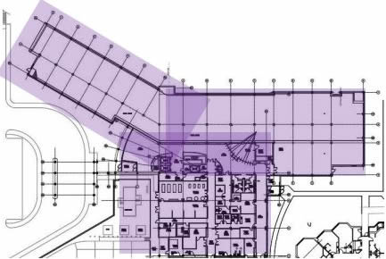
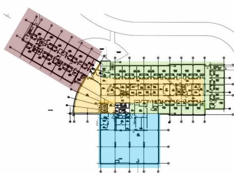
Each air handling unit delivers air to a designated area in the building. Air handling units were assigned in the following array:
 |
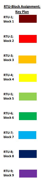 |
| Figure 1: First Floor air distribution |
 |
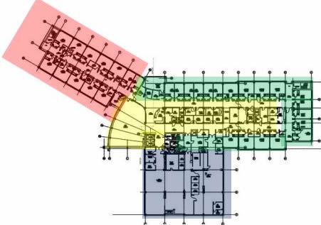
| Figure 2: Second Floor air distribution |
 |
| Figure 3: Third Floor air distribution |
In addition to the heating provided by the air handling units, heating is supplementally provided to eight hot-water cabinet unit heaters and eight hot-water unit heaters. The heating hot water is provided by three natural gas-fired boilers located in the first floor mechanical room.
Supplemental cooling is provided to the electrical room, two elevator machine rooms, one data room, and the vending room via five split system air conditioning units.
There exists, in future, a potential to mechanically connect the addition to the existing infrastructure. Upgrades would need to be made to existing campus chillers and steam boilers in order to adequately meet the load requirements inherent to the addition. |
| |
|
| L i g h t i n g |
The lighting design in the building is made up of fluorescent and compact fluorescent lamps. All ballasts are electronic.
Lighting fixtures in patient rooms are equipped with switching for ambient, reading, and examination settings and are provided with low voltage, local controls.
LED lighting is provided in emergency exit signs, and additionally supprted by 90-minute NiCad batter backs. |
|
| E l e c t r i c a l |
Incoming overhead power service is transformed from overhead 13.2 kV/3 phasepower to 480/3 phase underground power, which is connected to the building's main switchgear. From the main switchgear, power supply is branched to normal, critical, life safety, and emergency services. Power is further branched to equipment, having been transformed down to 208/120V 3-phase power.
The building contains one low and one high voltage automatic transfer switch, as well as one low and one high voltage distribution panel.
Services are additionally supported by a 1250 kW 480/277V/3 phase stand-by emergency generator.. |
| C o n s t r u c t i o n |
| The project was designed and constructed under a design-bid-build method. The $30 million, 101,115 gross sf addition was built between the years 2003 and 2006. As a mechanically and electrically stand-alone addition, construction did not impose on the function or operation of the existing structure. |
|
|
|
|