| |
|
|
| |
Building Statistics |
|
| |
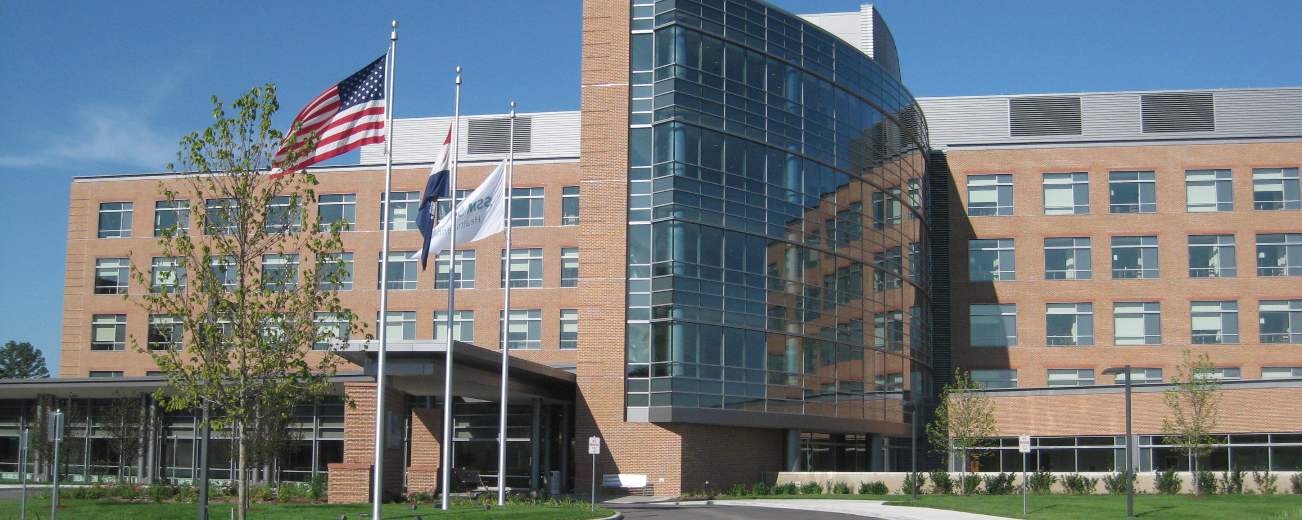
The SSM - St. Clare Health Center is located in a residential area of Fenton, Missouri. The building materials recall local aesthetics, but the building plan was largely free to develop organically and efficiently as no setbacks, street walls, or transportation paths were limiting factors. The lead architects on the project, HGA Architects and Engineers, designed the building with a programmatic focus. The design team used Lean principles traditionally seen in manufacturing facilities to streamline occupant workflows with the goal of reducing errors and saving lives. Patient room mockups were created during the design process so that employees could test layout options for maximum efficiency.
The building sits on a Seismic Design Category (SDC) D site. The condition of the site required that the building be broken up into eight structures separated by construction joints (in the construction documents labelled A through H). The structures come together to form a courtyard and also splay outward for additional glazed surface area, used to provide daylight for patient rooms |
|
| |
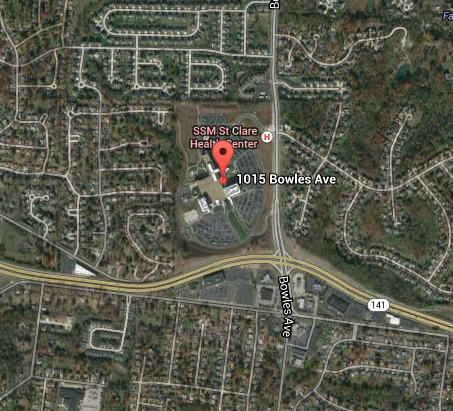
Figure 1: Surrounding Site and Neighborhoods, Courtesy of Google Maps |
|
| |
__________________________________________________________________________________________ |
|
| |
General Overview |
|
| |
Building Name: |
SSM – St. Clare Health Center |
Location: |
St. Louis County, Missouri |
Site: |
1015 Bowles Avenue Fenton, Missouri |
Occupant Name: |
SSM Health Care – St. Louis |
Occupancy Type: |
Medical, Medical Offices |
Occupancy by Code: |
Type I2 and B |
Size: |
427,000 square-feet |
Number of Stories: |
6 Floors above grade |
Construction Duration: |
September 2006 – March 2009 |
Budgeted Cost: |
$226.8 million |
Actual Cost: |
$223.5 million |
Project Delivery Method: |
Integrated (Lean) Project Delivery |
|
|
| |
__________________________________________________________________________________________ |
|
| |
Project Team |
|
| |
Owner: |
SSM Health Care – St. Louis |
General Contractor: |
Alberici Construction |
Construction Manager: |
Alberici Construction |
Architect: |
HGA Architects and Engineers |
Structural Engineers: |
HGA Architects and Engineers |
Mechanical Engineers: |
KJWW Engineering |
Consultants: |
Northstar Management, Hammes Company |
|
|
| |
__________________________________________________________________________________________ |
|
| |
Project Delivery |
|
| |
SSM Health Care developed an “Integrated Design Partnership Agreement” which included the owner (themselves), architect, and construction manager. The term “Lean project delivery” was used to describe the contract, which focused on mutual assumption of risk to facilitate more cooperation between the construction and design teams. The AIA A201, 1997 Edition of the Contract for Construction General Conditions served as the supplemental agreement for all situations not covered in the owner’s document. |
|
| |
__________________________________________________________________________________________ |
|
| |
Model Codes |
|
| |
Zoning: |
St. Louis County Codes and Ordinances |
Building Code: |
International Building Code (IBC) 2003 Edition |
Hospital Codes: |
Title 19, Division 30, Chapter 30 for Hospitals and Ambulatory Surgical Centers |
|
NFPA Life Safety Code (101) 2000 Edition |
|
AIA Guidelines for Design and Construction of Hospitals and Healthcare Facilities |
Fire Code: |
International Fire Code (IFC) 2003 Edition |
Mechanical Codes: |
International Mechanical Code (IMC) 2003 Edition |
|
International Gas and Fuel Code (IGFC) 2003 Edition |
Energy Code: |
International Energy Conservation Code (IECC) 2003 Edition |
Plumbing Code: |
St. Louis County Codes and Ordinances |
Electrical Code: |
National Electric Code |
Elevator Code: |
ANSI A17.1 Safety Code for Elevators and Escalators, 2000 Edition |
State Accessibility Code: |
Americans with Disabilities Act (ADA) |
|
|
| |
__________________________________________________________________________________________ |
|
| |
Building Enclosure |
|
| |

Figure 2: Brick Veneer and Glazing System, Courtesy of HGA Architects and Engineers |
|
| |
Brick Veneer |
|
| |
The exterior wall assembly is made up of a modular face brick over a steel stud back-up wall. From exterior to interior, exterior walls are composed of face brick, brick ties and air gap, extruded polystyrene insulation, cold formed metal framing, and interior gypsum board. Specified brick ties are X-Seal S.I.S anchors for steel studs and corrugated strap anchors. Two alternate wall constructions include a brick veneer over a CMU back-up wall and a brick veneer over a concrete back-up wall. These assemblies are largely similar except for the brick ties used to attach to different materials.
Other components of the brick veneer assemblies are lintels, flashing, and weep systems. Lintels over openings are precast concrete, possibly reinforcement for longer spans; flashing is self-adhering asphaltic rubber Perm-A-Barrier, laminated copper, or stainless steel; and weep systems are drainage fabric with cell vents made of flexible ultra violet resistant polypropylene co-polymer. |
|
| |
Glazed Curtain Wall |
|
| |
The curtain wall system is a grid of 2 ¼ inch aluminum horizontals and verticals which are thermally broken from the interior and are designed to tolerate both vertical and lateral motion. Panels holding glass are designed to deflect no more than L/300. The wall system must also tolerate expansion and contraction in temperatures ranging from 170 to 0 degrees Fahrenheit. The water tolerance is no less than 12 psf over the entire glazing system.
Glass on the building is Clear Low E Insulated Glass and Clear Tempered Low E Insulated Glass. Several windows have a stained glass appearance. These fenestrations are Decorative Low E Insulated Glass or have a Low E coating applied |
|
| |
__________________________________________________________________________________________ |
|
| |
Sustainability |
|
| |
From the Project Summary document Section 1.3A: “It is the philosophy of HGA and the Owner's desire to incorporate Sustainable Design into the Project to the extent deemed appropriate and attainable.” |
|
| |
________________________________________________________________________________ |
|
| |
System Technical Descriptions |
|
| |
Structural Systems |
|
| |
Foundations |
|
| |
Reinforced concrete drilled piers are required to support any column bearing more than 200
kips of compressive force, thus nearly every column on the project rests on a pier. The piers are connected by grade beams that run along the regular 30 ft x 30 ft. structural grid.
26 different pier
types are scheduled with diameters ranging from 3 ft. to 8 ft. Each pier is reinforced with spiral
reinforcement at 4 in. on center to a depth of three shaft diameters below the lowest grade beam, then
with #4 ties at 12 inches on center to the bottom of the pier. The depth of piers varies
between 16 ft. and 29 ft. Piers are 3000 psi concrete, have a bearing capacity of 40 ksf, and an assumed
skin friction capacity for tension of 2.5 ksf. |
|
| |
Framing |
|
| |
Framing is composite steel deck on composite steel members. Bay sizes in SSM St. Clare Health Center are surprisingly regular: typical bays are approximately 30 ft. square or 30 ft. by 32 ft., with some variation at edges and near curved architecture.
Floor deck and roof deck are both 3 in. 18 gage composite deck with 3 1/2 in. lightweight concrete topping. The roof is sloped with rigid insulation (up to 11 in.) which contributes a significant portion of the dead load.
Beams are mainly W16x26 or 18x35 wide flange members, the majority of which are
cambered between ¾ in. and 2 in. The girders are almost entirely 24 in. deep wide flanges with linear
weights varying between 55 lbs. and 94 lbs. depending on span and loading conditions. Columns range from W14x61 to W14x132 with splices 4 ft. above the second and fourth floors. |
|
| |
Lateral System |
|
| |
The structure is separated into 3 different segments by expansion joints. Throughout the structures, 4 types of lateral force resisting elements are used including special moment
frames (SMF), special concentrically braced frames (SCBF), special reinforced concrete shear walls
(SRCSW), and ordinary concentrically braced frames (OCBF). In the bed tower specifically, which is the focus of future thesis analysis, SMFs are used in the North-South direction and SCBFs and SRCSWs are used in the East-West direction.
The deck can be assumed as rigid for modeling purposes and distributes lateral shear forces into the lateral force resisting elements based on stiffness. In the bed tower, special shear reinforcement is used in the diaphragm concrete at the tower wing to ensure forces can reach collector points in the SMFs. |
|
| |
Mechanical Systems |
|
| |
SSM St. Clare Health Center has separate systems for thermal control and ventilation. Fan coil units in each patient room fed by central boiler and chiller system supply heating and cooling while a dedicated VAV outside air system provides ventilation.
The heating and cooling system consists of four natural gas fueled boilers and three cold water chillers. The boilers are two 300 BHP boilers with output capacity of over 1 million BTU/Hr, and two 200 BHP boilers with over 6.5 million BTU/Hr capacity. The cooling system is two 850 ton chillers and one 125 ton chiller. These supply hot and cold water to fan coil units in each patient room.
The dedicated VAV outside air system consists of seven air handling units. Four 75,000 CFM units serve the patient bed tower.
Since the hospital is in a high seismic area, most mechanical systems have some type of seismic detailing. The major systems such as natural gas piping, fuel oil piping, and ductwork are all detailed for anchorage to floors or roofs and for sway bracing. |
|
| |
Lighting |
|
| |
The majority of open-floor lighting in corridors and patient rooms are 2’x4’ diffused florescent troughs. Accent lighting includes architecturally-minimized halogen recessed lighting and single-row, multi-bulb wall washers. Exterior garden lighting includes mainly waist-high bollard lighting along pathways.
Emergency lighting was specified in all common egress spaces including corridors, stairwells, and discharge areas. Lit, directional exit signs were placed to keep occupants within 100 feet of the nearest sign. All egress lighting and exit wayfinding signage is supported by back-up generator power. |
|
| |
Electrical Systems |
|
| |
Electricity enters the patient bed tower through double ended switch gear connected to 3 phase, 4 wire, 4000 amp buses. The main transformers step down power from a primary 12.47 KV to 480/277V. Main buses directly feed the large equipment circuits such as the air handling units, boilers, chillers, and elevators. In addition, one of the bus lines feeds a secondary 1000 amp bus to the normal power distribution, while the other supplies a secondary 600 amp bus to the “critical” power distribution. These secondary buses are also 3 phase, 4 wire at 480/277V. Transformers in local electrical rooms step the power down again from 480 to 208/120V before distribution to individual panels.
Because the building is a hospital, a complex system of 5 automatic transfer switches ensure constant power delivery to life safety systems, air handlers, elevator systems, and critical medical rooms such as the ICU. Two 2000KW generators are capable of sustaining the building for up to 90 minutes. |
|
| |
Construction |
|
| |
SSM St. Clare Health Center was contracted with an integrated project delivery method and constructed from September 2006 to March 2009. The total budgeted cost was $226.8 million, but the construction team was able to complete the building for only $223.5 million for a savings of $3.3 million.
During construction, noise control procedures were specified to mitigate problems with surrounding residents. Smoking was prohibited on the site to comply with hospital policies and avoid contaminating the patient rooms. |
|
| |
Telecommunications and Security Systems |
|
| |
Twelve telecommunications rooms are located throughout the hospital. These rooms service a card access security system, closed circuit camera system, and comprehensive nurse call system, as well as the various common telecommunication systems such as internet, telephone, and radio systems. The penthouse floor above the patient bed tower houses a satellite radio antenna, hear radio antenna, satellite telephone antenna, and satellite television dish that serve the entire building. |
|
| |
Circulation |
|
| |
Because SSM St. Clare Health Center is so large (over 400,000 gsf) and composed of multiple structures, circulation will be discussed for only the patient bed tower. The main entrance to the patient bed tower is beneath the outward-jutting tower wing. The tower itself has stairwells on wither of the farthest ends and an elevator core of 3 elevators and a stairwell at its center. A monumental staircase in the atrium provides a fourth means of egress to occupants on the second floor. |
|
| |
Fire Protection |
|
| |
Fire protection systems in SSM St. Clare Health Center were designed to meet the requirements of the 2003 Edition of the International Fire Code. The hospital is fully sprinkled with an automatic sprinkler system rated to begin irrigation at 155 degrees Fahrenheit. Activation of the sprinkler system also simultaneously activates the fire alarm system and transmits the signal to the fire alarm control panel monitored by an off-site service. In the patient bed tower, more than 400 sprinklers per floor were specified in multiple zones. The atrium area was zoned separately on all floors. In terms of coordination in plenum space, the sprinkler piping was hung from the bottom of the steel framing and not the floor deck. The fire protection systems were detailed for seismic anchorage and sway bracing.
Standpipes were provided throughout the building. On each stair landing, 2-1/2 inch Class I standpipe outlets were specified. Portable fire extinguishers were provided according to NFPA 10 to satisfy a maximum occupant travel distance to the nearest extinguisher of 75 feet. |
|
| |
|
|
| |
Note: While great efforts have been taken to provide accurate and complete information on the
pages of CPEP, please be aware that the information contained herewith is considered a work-in-progress for this thesis project. Modifications and changes related to the original building designs and
construction methodologies for this senior thesis project are solely the interpretation of Christopher
Brandmeier. Changes and discrepancies in no way imply that the original design contained errors or was
flawed. Differing assumptions, code references, requirements, and methodologies have been
incorporated into this thesis project; therefore, investigation results may vary from the original
design. |
|
| |
|
|