Northeast Hospital Expansion
123 Medical Lane, USA
Building Statistics Part 1
General Building Data |
|
Building Name |
Northeast Hospital Expansion |
Location and Site |
123 Medical Lane, USA |
Building Occupant Name |
Trinity Health |
Occupancy or Function Type |
IBC 2009 I-2: Hospital |
Size |
|
Total Stories |
10 Stories |
Owner |
|
Owner Representative |
KLMK Group (now CBRE Group) |
Construction Manager |
|
Architect |
|
MEP FP Engineers |
|
Civil Engineers |
|
Structural Engineers |
|
Mechanical Contractor |
|
Electrical Contractor |
|
Construction Start Date |
January 2013 |
Construction Finish Date |
September 2015 |
Actual Cost Estimate |
$230,000,000 |
Project Delivery Method |
CM @ Rsik GMP with Design Assist |
Architecture:
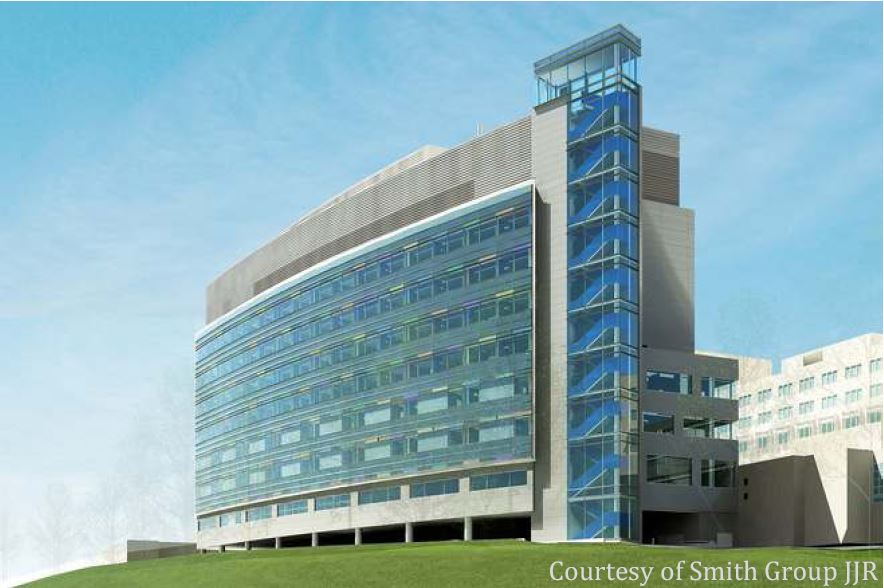
The Northeast Hospital Expansion includes the construction of a new ten story patient tower, central utility plant and a four-level parking garage. The patient tower allows for 180 new private patient rooms. Patient floors include floors one through six, each floor houses 30 patient rooms with the sixth floor reserved for future growth. Mechanical equipment occupies the basement and floors seven through ten. The ground floor allocates space for the linen storage, biowaste room, autopsy room, body holding room, and electrical equipment. A connection bridge on the ground floor lets occupants transverse between the new patient tower and the rest of the hospital campus. The design also allows for deliveries and vehicular traffic The exterior of the patient tower curves to maximize use of the land and the entire structure wears a glimmering blue curtain wall at patient occupied floors and metallic louvers enclose the top four floors of mechanical space.
Major National Codes Utilized:
- IBC (International Building Code) 2009
- International Mechanical Code 2009
- National Electric Code 2008
- International Plumbing Code 2009
- International Fuel Gas Code 2009
- Healthcare NFPA 99
Zoning:
Zoning map courtesy of the local planning board
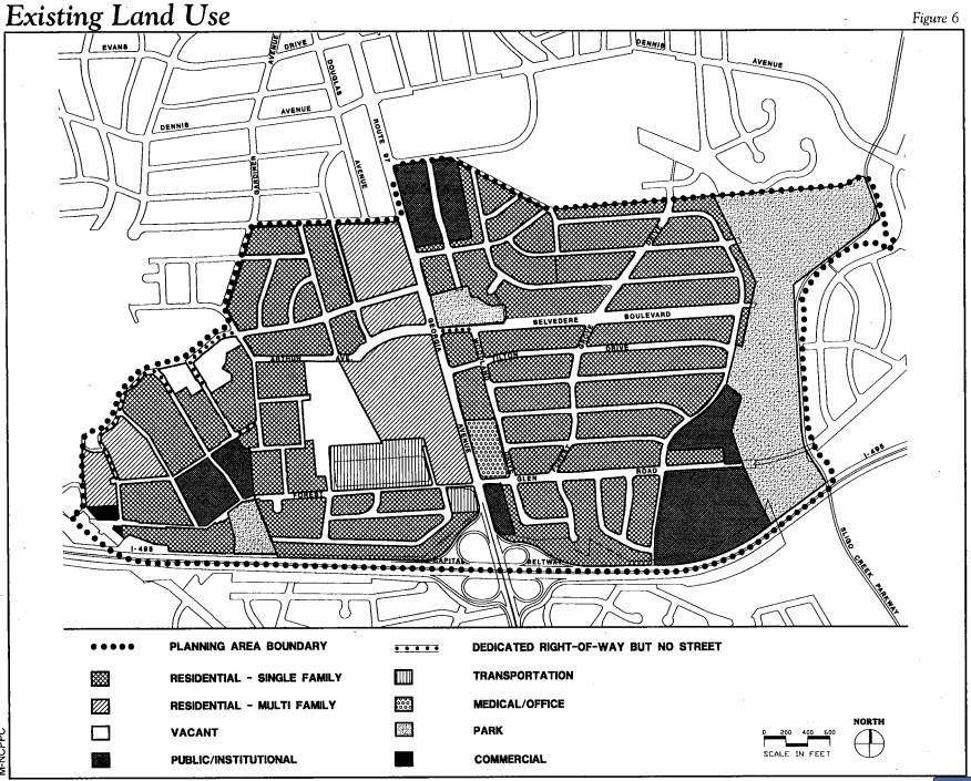
Northeast Hospital Expansion occurs on the large commercially zoned section in the lower right of the above zoning map. The site neighbors inhabited single family residential that adopted quite hours from Friday night until 9am Saturday morning. To the west of the site, zoning deemed the land for park space. The expansion falls under C-2 type zoning, which requires a maximum floor ratio of 1.5. There are no historical requirements for the expansion.
Build Façade:
The exterior façade of the Northeast Hospital Expansion contains four main wall types. The South, East and West walls from the ground floor to the sixth floor of the structure receives a curtain wall composed of 1 5/16” triple grazed insulated glass units (IGU) for noise reduction from the adjacent highway. The IGU’s remain attached to the structure through mullions. A variety of glazing colors liven the exterior, ranging among blue, green, orange, rose, and yellow, but the most commonly used glazing is the clear laminate vision glazing. Spandrel glazing between floors masks the structure behind giving the building a continuous glimmer in the sun. Between the spandrels glazing and structure 4” of mineral wool insulation with an aluminum foil faced vapor retarder exists providing additional thermal and moisture resistance.
At the mechanical floors located at the top of building, more of a variety of wall types exist. Transitioning from the curtain wall on the sixth floor to the seventh floor mechanical space on the south facing wall, metal louvers clip fasten to 6” louver support framing and receive an insulated blank off panel. The east and west walls at this transition area obtain a 4” corrugated metal panel with fluid applied air barrier, 2” of insulation core material back up panel clip fastened to 8” of metal stud. The metal stud then gains 5/8” gypsum sheathing. On the north wall, primarily 3” of insulated metal panel clads the structure. The insulated metal panels clip fasten to 8” metal studs accompanied by a weather and air barrier, gypsum sheathing and ERS with 1 ½” rigid insulation. The insulated metal panel wall type covers a majority of the north-facing wall.
Roofing:
Three different types of roofing enclose the roof of the Northeast Hospital Expansion. The portions of the patient tower’s roof used for the walkway toward the mechanical roof top units uses built-up asphalt with a vapor barrier and 3” of tapered insulation sloped at ¼” per foot towards the roof drains. The rest of the patient tower roof is covered in a green roof made from growing media, filter fabric drainage board, 3 ply cold applied roofing system, sheathing, 3” of rigid insulation and a vapor barrier. Finally portions of the existing hospital space undergoing renovations receive another green roof system. The renovation green roof includes growing media, filter fabric drainage board, fleece back TPA Root Barrier set in water based adhesive, single ply trilaminate water proofing felt set in solvent free adhesive, 5/8” DensDeck set in green biobased foam insulation adhesive, quick dry primer, and then the existing three ply of built-up roof system.
Sustainability:
The design for the Northeast Hospital Expansion aims for LEED Silver. To achieve this level of sustainability, the project team utilizes several methods. Beyond just meeting the necessary pre-requisites such as testing and balancing of the HVAC to verify compliance with ASHRAE 62.1 and 90.1, the use of regional materials and the recycling of construction waste become key. Composite woods may not contain any urea formaldehyde and insulation may adhere only by solvent cements and adhesive primers. The domestic water pumps must comply with ASHRAE/IESNA 90.1 and healthcare plumbing fixtures must consume water in compliance with credits WE 1 and WE 3 for water use reduction. A green roof covers the top of the building to reduce the heat island effect and aid in storm water treatment. Finally by implementing single door pharmacy refrigerators with high efficiency top mounted refrigeration, the project team aims for an innovation credit.
Building Statistics Part 2
Construction:
The Northeast Hospital Expansion project received its notice to proceed on January 8th, 2013 and expects to undergo construction until complete for occupancy move in on the sixth floor September 6th, 2015. In the projects entirety, a total duration of 733 days need to occur. The first phase of the project is the excavation in which there will be an assembly line of dump trucks circling the hospital to haul dirt. The second is the construction of the superstructure. Here there will be a tower crane constructed and a material hoist to lift material to the guys working on the upper floors. The final phase change will occur when the building becomes fully enclosed and the lay down areas move to their specific floors within the structure.Work flows in a zigzag pattern from north to south movingfrom the west to the east starting at the ground floor and moving up. At this point in time there is no longer a need for the tower crane since the building is fully enclosed and all of the heavy lifts havebeen completed. The material hoist has also been dismantled since the elevators in the building are now operational.
Structure: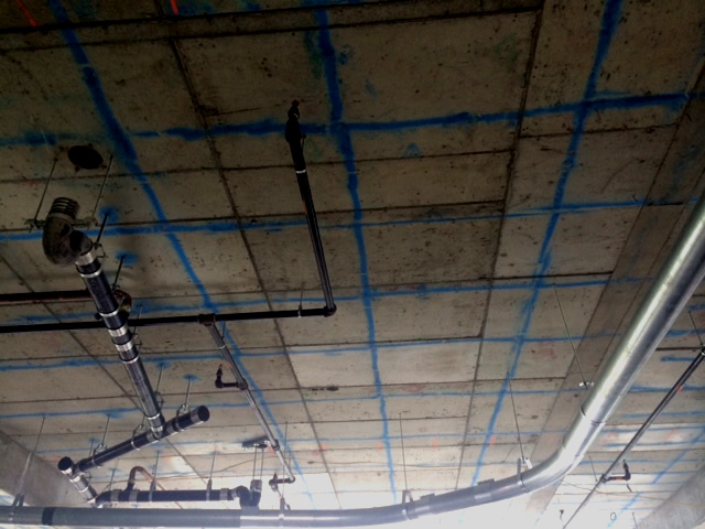
The superstructure is composed primarily of reinforced concrete columns supporting 10 1/2" thick slabs. All of the concrete slabs above the ground floor are post tensioned. To avoid drilling through the tensioned tendons the post tensioned slabs have been painted with the tendon locations. The concrete columns have a concrete strength of 4000psi and the slabs have a concrete strength of 3500psi. In total there will be 4026 CY of concrete, 1065.3 tons of reinforcement, and 12 tons of post-tensioning tendons. Once the structure reaches the mechanical penthouse levels, the struccture switches from concrete to hollow structural steel tubing.
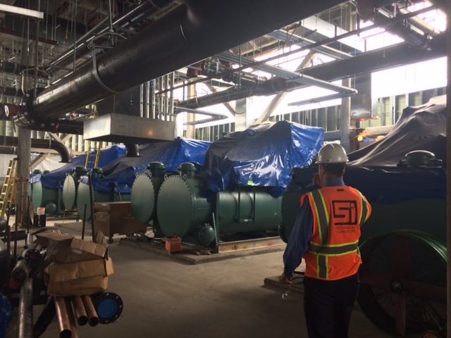
Mechanical:
The building is heated and cooled by a typical boiler and chiller system located in themechanical penthouse. The chill water lines and hot water lines run out to fan coil units and radiant fin terminal units located through out the patient tower. High pressure steam and medium pressure steam are supplied to the rest of the campus by being piped from the mechanical penthouse down to the basement of the patient tower and through utility tunnels located to the north wall of the patient tower. Medical gas, nitrogen, oxygen, and carbon dioxide are also supplied to each patient room. The majority of AHU’s are located in the mechanical penthouse with the exception of the autopsyunit. The autopsy unit is located in the basement and requires pre-filters and HEPA filters. The air supplied to theautopsy rooms is then 100% exhaust.
Electrical: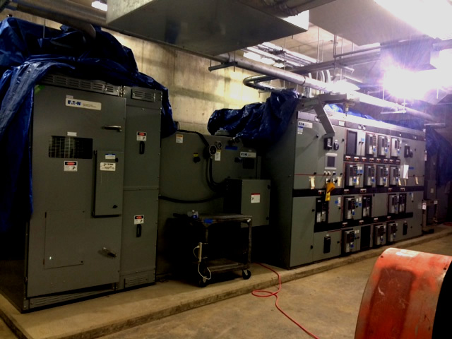
Electrical distribution is accomplished by a 13.2kVA, 12000A, 750MVA, 3 phase, primary incoming utility switchgear located in the basement. The power is then stepped down to a 480/277V and distributed to three substations of 25000kVA, 480/277V and one substation of 2000kVA, 480/277V for the chillers in the pent house. From the substation electricity is distributed by separate lines to independent transformers at each piece of equipment or directly to the panels located on each floor. There are three 2000kW generators with an emergency switchgear to be utilized for critical zones within the hospital in the event of a power outage to the campus. Lighting is accomplished by basic fluorescent tube lighting with occupancy controls.