Building Statistics
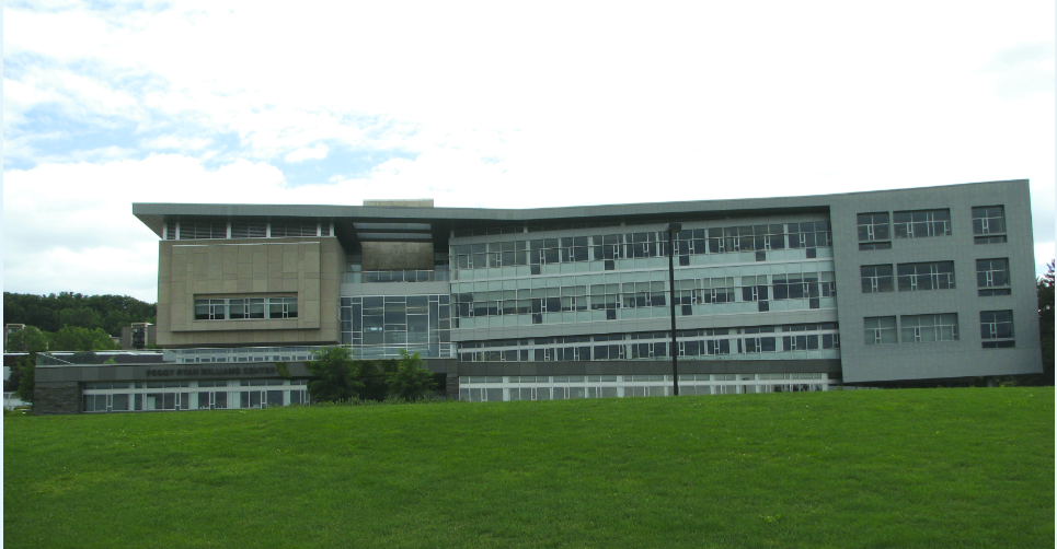
Ithaca, New York | Angela Mincemoyer | Structural

| Building Name | Peggy Ryan Williams Center |
| Location & Site | Ithaca, New York |
| Building Occupant Name | Ithaca College |
| Occupancy | Office Use |
| Size | 58,200 square feet |
| Number of Stories | 4 stories (all above grade) |
| Dates of Construction | Start Date: awaiting response from Christa Construction
End Date: awarded substantial completion in March 2010; by November 2010, all work completed |
| Actual Cost | Construction cost was billed at approximately $19.3 million. |
| Project Delivery Method | Design-Bid-Build |
| Owner | Ithaca College |
| Architect | Holt Architects |
| Structural Engineers | Ryan-Biggs Associates |
| Mechanical & Electrical Engineering | Delta Engineers |
| General Contractor | Christa Construction |
| Geotechnical Engineer | CME Associates, Inc. |
| Landscape Architects, Planners | Trowbridge & Wolf |
| Engineers and Surveyors | T.G. Miller |
| Energy Modeling | Erdman Anthony and Associates |
| Environmental Design Consulting | Atelier Ten |
| Audio, Visual & Acoustical Consulting | AVL Design |
| Fire and Smoke Consulting | John H. Klote |
| Geothermal Engineering | Earth Sensitive Solutions |
| Lighting Design | Naomi Miller Lighting Design |
Traditionally, the Ithaca College campus does its best to follow the style of architecture that is contemporary with the time period. This characteristic may be seen in the neighboring buildings around campus which date back to the 1970’s. With the global push towards sustainability, the college decided that it was important to show that Ithaca College was moving forward with the times, being eco-friendly, and wanting to incorporate their beautiful surroundings into the campus design. This led to a new era of architecture at Ithaca campus, beginning with the Park School of Business. After the Park School of Business was designed, the Peggy Ryan Williams Center was the next step in the process. |
The Peggy Ryan Williams Center is a key aspect of fulfilling this new era because it is seen as a gateway to the college. Its occupants consist of the college’s admissions as well as numerous administrative offices. The building is also one of the first views that may be seen upon arriving to the campus. Therefore, Ithaca College saw the building as a way to show perspective students, employees, and visitors that their college was moving forward to be more “green” and incorporate the surrounding nature. |
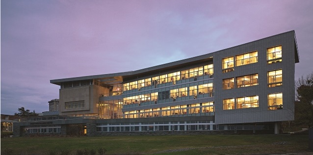
The architecture of this building may at first seem a little obscure and jagged. However, the architects did not simply want the building to stand out from the rest. Numerous aspects of the appearance of the building were driven by their desire to be eco-friendly. The many large areas of glass are present in order to allow for breath-taking views of the nearby Cayuga Lake. By allowing the windows to be as large as possible, it also helps the buildings’ occupants to feel as if they are a part of the nature around them. |
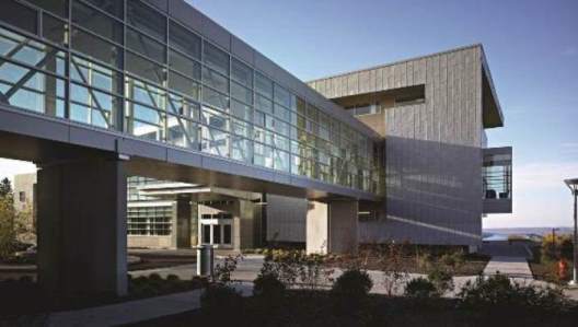
Another feature of the Peggy Ryan Williams Center is the pedestrian bridge which can be viewed in Image 2 below. The bridge allows its users to easily navigate from the PRWC to the Dillingham Center without going outdoors. |
Major National Code: 2002 Building Code of New York State (BCNYS) |
Zoning: Maximum permitted coverage increase: 20% |
Maximum building height: 76 feet |
Zoning was governed by the town of Ithaca. |
Historical Requirements: No historical requirements were present. |
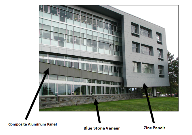
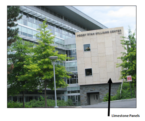
| Building Facades: | The façade of the Peggy Ryan Williams Center consists of five main materials: zinc panels, blue stone veneer, composite aluminum panels, limestone panels, and various types of glass. These materials can all be found on various parts of the building, some examples may be viewed below (Images 3 & 4). In most cases, the exterior skin consists of cold-formed metal studs backing up insulated metal panel systems or limestone panels, where present. As seen in the photograph below, the building entails large areas of glass; these areas are either curtain walls or storefront windows. The glass curtain walls were stick-built on site, while the storefronts are panelized. The main difference between these two types is that the storefront generally spans 10 feet or less and the curtain wall may span further. The types of glass include annealed float glass, heat-treated float glass, sputter-coated float glass, wired glass, and laminated glass. |
| Roofing: | There are two main roofing systems used for the Peggy Ryan Williams Center. Variations of the standard membrane roofing are the main type of system. As seen below (Image 5), a ½" substrate board sits on top of the metal roof deck. This is then followed by a vapor retarder, 4" polyisocyanurate insulation, ½" cover board, and finally topped off with thermoplastic polyolefin (TPO) roofing membrane. The first floor roof is an intensive green roof which building occupants are able to go out and relax on while enjoying views of the Cayuga Lake. The green roof may be seen in the section view (Image 6) and pictures below (Images 7 & 8). The main components of the green roof include hot fluid applied roofing, a root barrier, drainage composite, 4" extruded polystyrene insulation, a moisture mat, water retention composite, and finally vegetation and plating medium. |


LEED Platinum is the prestigious title that the Peggy Ryan Williams Center was awarded. However, this title did not come without a lot of planning and sustainability considerations. As previously mentioned, most of the architectural appearance of the building was governed by sustainability. Some examples include the main roof taking on a slight "V" shape as to help collect rain water, the atrium being designed to help with natural ventilation, green roofs, geothermal heat wells, solar shading, and many large areas of glass to allow for day lighting. |
| Rain Water Collection: | As can be seen in the Image 9 below, the roof forms a "V" in order to help promote rain water collection. The rain water will then be used throughout the building as a gray water supply. Because the building is designed in various ways to help with this rainwater collection (not just the "V" shape of the roof) the collection is able to provide 90% of the buildings annual water consumption (see Image 10 below). |


| Day Lighting: | Vast regions of glass allow for day lighting, thus resulting in a lower lighting load. The large atrium space within the core of the building also enables the natural light to reach further into the building. |
| Green Roof: | As previously mentioned, the first floor roof is a green roof. This region helps to reduce the amount of impermeable ground that the building footprint removed from the area. The green roof also provides a nice area for employees and visitors to relax, enjoy nature, and look at the beautiful Cayuga Lake. |
| Natural Ventilation: | The mechanical load is lessened by utilizing the natural ventilation capabilities of the large atrium. The air flow may be viewed in the following diagram (Image 11). |

| Solar Shading: | Solar shading elements may be seen on both the south and the west sides of the building. In order to help the occupant's on the upper floors, the roof was extended to provide solar shading. Sunshades were also added to the building's south and west sides (these can be seen in the Image 12 below). |

| Structural: | Foundation System:Columns, piers, and drilled piers support the foundation for the PRWC. The foundation walls themselves range from 1'-0" thick with 3'-0" wide footings to 1'-8.5" thick with 6'-0" wide footings. In areas where the footings alone cannot reach down to competent bedrock, piers and then drilled piers are used. Most areas of the building are provided with a 5" concrete slab-on-grade. In various portions of the building, grade beams are utilized to transfer the loads of braced frames and bearing walls from above (stairwell and elevator shaft), and to help tie back the column supporting the overhang in the north corner of the building. The grade beam sizes range from 12" wide and 36" deep to 51" wide and 48" deep. Loads from the grade beams are then transferred to piers and in turn to the drilled piers in order to finally reach competent bedrock. Pier depths range from simply resting on top of the bedrock to being drilled 4'-0" below the surface of the bedrock. |
Framing System:The structural system components are fairly common; however, their placement and size variations make the framing irregular. The roof of the building is constructed of roof decking, which spans perpendicular to the steel wide flange beams, girders, and columns. The floor of Level 1 through Level 3 consists of composite decking and steel wide flanged beams, girders, and columns as well. Various beams and girders are provided with shear studs for composite action. Sizes and spans of the wide flanges vary greatly throughout the building and even throughout a single floor framing system. At locations where the building cantilevers, moment connections and larger beam/girder sizes make the cantilevers possible. |
Lateral System:In both the North-South and the East-West directions, concentrically braced structural steel frames resist the lateral load. Braced frame columns are typically W10s, while HSS6x6x3/8 are commonly used for the diagonal braces. Various braced frames are provided in the north-south direction to resist the lateral loads. However, in the east-west direction, there is a lack of effective braced frames. In order to resist unbalanced loads there should be at least two (staggered) frames in each direction. |
| Electrical: | The preexisting underground 15KV service was rerouted to service the Peggy Ryan Williams Center. The primary service is also comprised of a 1000KVA transformer and a 1600 amp, 480/277V, 3-phase, 4 wire main distribution switchboard. From there, the current goes into six main panels, including one main power panel, one lighting panel, one computer panel, one main emergency panel, and two main standby panels. A natural gas-powered generator specified at 437.5KVA, 277/480V, 3-phase, 4 wire provides back up power to each emergency and standby system. Each circuit consisting of single receptacles are rated at 20 amps. Circuits which contain multiple duplex receptacles are rated at 15 amps. |
| Lighting: | All of the building's lighting fixtures are 277V. The majority of the lamps are fluorescent. However, some incandescent and LEDs were used. In order to reduce the building's energy consumption, all rooms, except the bathrooms, utilize ceiling-mounted occupancy sensors. Due to the large areas of glass on the building's façade, day lighting controls were also considered in the project. |
| Mechanical: | A closed loop geothermal system is the building's primary heating and cooling source. This system is located adjacent to the building. There are two dedicated outdoor air units, one to supply the east end of the building, and one to supply the west end of the building. Each DOA unit utilizes an energy recovery wheel. This will aid the system by extracting energy from the exhaust air. A separate air handling unit is present to exhaust the mechanical room, which is located on the Garden Level. Each room of the building has its own heat pump. The majority of the heat pumps have a 670 cfm capacity. However, the heat pumps which supply open office spaces and corridors have a 900 cfm capacity. |
| Construction: | The project delivery method was design-bid-build. Christa Construction served as the general contractor. However, because the building was constructed during hard economic times, the architect, Holt Architects, took on some of the traditional construction management roles. The construction cost of the 58,200 square foot office building was billed at approximately $19.3 million dollars. The project was awarded substantial completion in March of 2010 and by November of that year all work was completed. |
| Fire Protection: | The Peggy Ryan Williams Center fire protection consists of a combined standpipe/wet pipe sprinkler system. Both of these were designed in accordance with the New York Building Code. The sprinkler system was also designed in accordance with the NFPA 13 (1999) while the standpipe system was designed according to the NFPA 14. All sprinkler heads are quick-response with a 135 degree rating. |
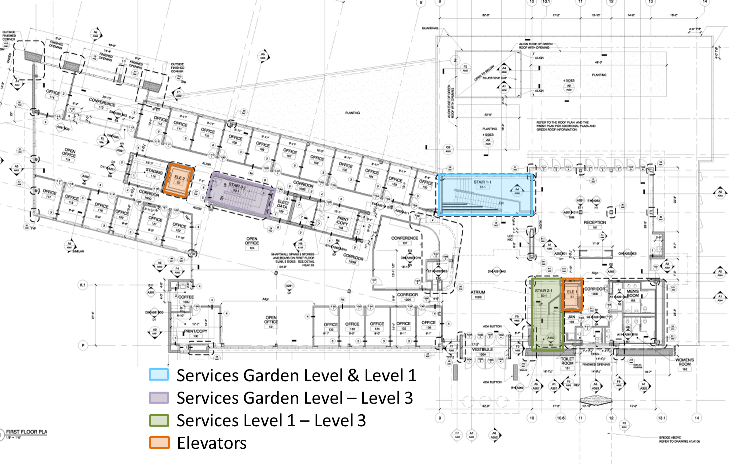
| Transportation: | Two elevators and three stair towers provide transportation throughout the building. The locations of these items may be viewed below on Image 13. The central stair tower only services the Garden Level (ground level) and Level 1. The stairs in the east end of the building service Levels 1, 2, and 3. The stair tower on the west end of the building services all floors of the building (Garden Level, Level 1, 2, and 3). Two sets of elevators are provided for transportation on all levels of the building. These elevators are rated at a 3500 pound load and a 200 fpm speed. |
| Telecommunications: | In order to service the office building's various telecommunication needs, combination telephone and data outlet boxes are located in each office and conference room. To accommodate spaces with a larger demand, such as some conference rooms and meeting rooms, multiple boxes are provided. |
This page was last updated on 12-17-13, by Angela Mincemoyer and is hosted by the AE Department © 2014 | Template Design: HTML5Templates.com